


G3X Installation Manual – GTP 59 Page 5-3
190-01115-01 Revision A
5.4 Installation Considerations
5.4.1 GTP 59 Icing
The GTP 59 OAT probe has no icing protection. If ice accumulates on the GTP 59 OAT probe, its
accuracy is unknown. Consequently, air temperature measurements may be incorrect if ice accumulates
on the probe. Furthermore, computations dependent upon air temperature measurements may be affected
(e.g. true airspeed and delta-ISA).
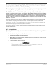
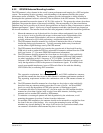
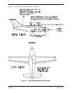
5.4.2 GTP 59 OAT Probe Installation
NOTE
The following instructions are general guidance.
NOTE
Do not mount the GTP 59 where aircraft exhaust gases will flow over it.
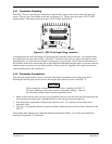
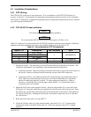
Table 5-5 contains a list of parts needed for the GTP 59 installation and interconnect harness. Reference
numbers in the table and instructions refer to item bubble numbers shown in Figure C-4.1.
Table 5-5. Parts Needed for GTP 59 Installation
Figure C-4.1 Description Qty. Included GPN
1 Ring Terminal
2 3-Conductor Cable
3 OAT Sensor
1 494-00022-xx
4 Nut 1 210-00055-00
5 Washer 1 212-00026-00
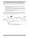
1. Prepare the surface. The metal body of the OAT probe should be grounded to the aircraft. The
installation requirements vary depending on the airframe material composition.
a. Aluminum airframe: When a mounting location has been found, prepare the inside surface of
the aircraft. Remove all paint from the contacting area and clean with a degreaser.
b. Composite airframe: If possible, mount the OAT probe through a grounded metal strap or
band. Otherwise, mount the OAT probe in an area of the airframe that has a significant
amount of underlying metal foil or mesh. To ensure adequate conductivity, it may be
necessary to mount the OAT probe through a metal doubler. Use fasteners that allow a
conductive path to the airframe.
2. Mount the OAT probe on the prepared surface. Place the ring terminal (2) over the end of the
OAT probe (4). Insert the probe and ring terminal into the hole in the skin of the aircraft. Place
the washer (6) over the end of the OAT probe on the outside skin of the aircraft. Thread the nut
(5) onto the OAT probe. Holding the OAT probe on the inside, tighten the nut (5) to 100 inch-
lbs. ±20 inch-lbs.
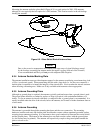
3. Route the OAT probe cable (3) to the GSU 73.
4. Cut the OAT Probe cable (3) to the required length. Strip back 2.0” to 3.5” of jacket while
retaining the shield on the OAT Probe cable (3). Trim away enough to leave 0.5” of shield
exposed.