


Page 5-4 G3X Installation Manual – GTP 59
Revision A 190-01115-01
5. Strip back 1/8” (0.125”) of insulation and crimp pins (11) to each of the conductors in the
shielded cable.
6. Cut an AWG #16 (8) wire to 3” long. Strip back 0.5” of insulation from this cable. Connect the
shield of the OAT Probe cable (3) to the AWG #16 wire (8).
7. Attach the ring terminal (9) to the backshell, using the screw provided in the OAT Probe Kit (10)
and one of the tapped holes on the backshell termination area.
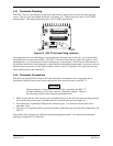
8. Insert newly crimped pins into the D-Sub connector and wires (3, 11) into the appropriate
connector housing location (12, 7) as specified by the installation wiring diagrams.
9. Verify that all necessary pins for the GSU 73 have been attached to the cables and snapped into
the proper slots of the 78 pin D-Sub connector.
10. Wrap the cable bundle with Silicone Fusion Tape (GPN: 249-00114-00 or a similar) at the point
where the backshell strain relief and cast housing contact the cable bundle. The smooth side of
the backshell strain relief should contact the tape.
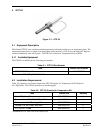
5.5 Unit Installation
Refer to Figure C-4.1 GTP 59 O.A.T. Probe Wiring Detail for wiring and mounting instructions.
5.6 Maintenance
Maintenance of the GTP 59 is “on condition” only. Periodic maintenance of the GTP 59 is not
required.