


G3X Installation Manual – Antennas Page 6-7
190-01115-01 Revision A
6.4 Teardrop Footprint Antenna Installation (GA 55 and GA 56)
This section describes the structural mounting of the teardrop footprint antenna installation.
An acceptable installation method is to use Garmin P/N: 115-00846-10 doubler plate with the GA 55 or
GA 56 stud mount antennas. Another acceptable method is to fabricate and install one of three doublers
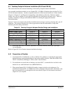
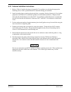
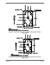
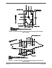
(Figure 6-4, Figure 6-5, and Figure 6-6), depending on the thickness of the skin. The three doubler
designs vary only by number of rivets and hole preparation for installation with flush rivets. Table 6-5
provides a summary of design and installation details for selecting the appropriate antenna
doubler/backplate.
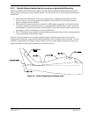
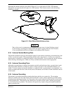
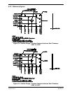
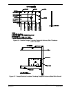
Figure 6-7 shows an example of the doubler installed between stringers on the top fuselage skin, just off
centerline. The location should be flat, with no gaps between the skin and doubler, to keep from
deforming the skin during installation.
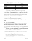
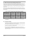
Table 6-5. Teardrop Footprint Antenna Doubler Design and Installation
Aircraft Skin Thickness 0.032” to 0.049” 0.049” to 0.051” 0.051” to 0.063”
Doubler Design (Figure)
Figure 6-4 Figure 6-5 Figure 6-6
Number of Rivets Required
12 16 16
Type of Rivets Required
1
MS20426AD4-x MS20426AD4-x MS20426AD4-x
Skin Preparation for Rivets
Dimple Dimple Countersink
Doubler Preparation for Rivet
s
Countersink Countersink None
Skin Cutout Detail (Figure)
Figure 6-8 Figure 6-9 Figure 6-10
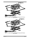
Doubler Installation (Figure)
Figure 6-11 Figure 6-12 Figure 6-13
Notes:
1. Rivet length determined at installation, dependent on thickness of material (rivet length = grip length +
1.5*rivet diameter)
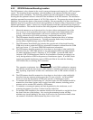
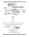
Refer to Figure B-2.X for Garmin Antenna installation drawings.
6.4.1 Preparation of Doubler
1. Use Garmin P/N: 115-00846-10, or refer to Table 6-5 for guidance on selecting the appropriate
doubler drawing based on the thickness of skin at the antenna location. Make the doubler from
2024-T3 Aluminum (AMS-QQ-A-250/5), 0.063” sheet thickness.
2. For installation in aircraft skins of thickness less than 0.051”, countersink the rivet holes in the
doubler for use with flush head rivets (MS20426AD4-x).
3. When using Garmin P/N: 115-00846-10 doubler, sixteen rivet holes exist in the part. For
installation of Garmin P/N: 115-00846-10 in skins of thickness between 0.032” and 0.049”, only
the rivets identified for use through the skin cutout detail (Figure 6-8) and doubler installation
(Figure 6-11) are required.