


G3X Installation Manual – Antennas Page 6-3
190-01115-01 Revision A
6.3.2 GPS/XM Antenna Mounting Location
The GPS antenna is a key element in the overall system performance and integrity for a GPS navigation
system. The mounting location, geometry, and surroundings of the antenna can affect the system
performance and/or availability. The following guidance provides information to aid the installer in
ensuring that the optimum location is selected for the installation of the GPS antenna. The installation
guidelines presented here meet the intent of AC 20-138A section 16. The greater the variance from these
guidelines, the greater the chance of decreased availability. Because meeting all of these installations
guidelines may not be possible on all aircraft, these guidelines are listed in order of importance to achieve
optimum performance. Items 1-4 below are of equal importance and their significance may depend on
the aircraft installation. The installer should use their best judgment to balance the installation guidelines.
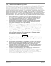
1. Mount the antenna on top of the aircraft in a location with an unobstructed view of the
sky, as close to level as possible with respect to the normal cruise flight attitude of the
aircraft. If the normal flight attitude is not known, substitute the waterline, which is
typically referenced as level while performing a weight and balance check.
2. The GPS antenna should be mounted in a location to minimize the effects of airframe
shadowing during typical maneuvers. Typically mounting farther away from the tail
section reduces signal blockage seen by the GPS antenna.
3. The GPS antenna should ideally be located at the opposite end of the aircraft from the
COM unit in order to make the GPS less vulnerable to harmonics radiated from the COM
itself (see Section 1.7.3 for more GPS/COM interference information).
4a. The GPS antenna should be mounted no closer than two feet (edge to edge) and ideally
three feet from any VHF COM antenna or any other antenna which may emit harmonic
(or other) interference at the L1 frequency of 1575.42 MHz. An aircraft EMC check
(reference VHF COM interference check in Post Installation Checkout procedures) can
verify the degradation of GPS in the presence of interference signals. If an EMC check
reveals unacceptable interference, insert a GPS notch filter in line with the offending
VHF COM or the (re-radiating) ELT transmitter.
NOTE
The separation requirement does not apply to GPS and COM combination antennas,
provided the antenna has been tested to meet Garmin’s minimum performance standards.
The separating requirement includes the combination with an XM antenna element as
well.
4b. The GPS antenna should be mounted no closer than two feet (edge to edge) and ideally
three feet from any antennas emitting more than 25 watts of power. An aircraft EMC
check can verify the degradation of GPS in the presence of interference signals.
4c. To minimize the effects of shadowing at 5° elevation angles, the GPS antenna should be
mounted no closer than 6 inches (edge to edge) from other antennas, including passive
antennas such as another GPS antenna or XM antenna.
5. To maintain a constant gain pattern and limit degradation by the windscreen, avoid
mounting the antenna closer than 3 inches from the windscreen.
6. For multiple GPS installations, the antennas should not be mounted in a straight line from
the front to the rear of the fuselage. Also varying the mounting location will help
minimize any aircraft shading by the wings or tail section (in a particular azimuth, when
one antenna is blocked the other antenna may have a clear view).