


Page B-26 G3X Installation Manual – Appendix B
Revision A 190-01115-01
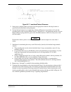
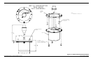
Preferred Method
Slide a solder sleeve (item 5) onto the prepared cable assembly (item 4) and connect the flat braid
(item 6) to the shield using a heat gun approved for use with solder sleeves. It may prove beneficial
to use a solder sleeve with a pre-installed flat braid versus having to cut a length of flat braid to be
used. The chosen size of solder sleeve must accommodate both the number of conductors present in
the cable and the flat braid (item 6) to be attached.
NOTE
Reference Section B.3.2 for recommended solder sleeves and heating tools. The same
recommendations are applicable to this technique.
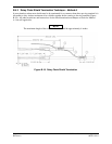
Secondary Method
Solder a flat braid (item 6) to the folded back shield on the prepared cable assembly (item 4). Ensure
a solid electrical connection through the use of acceptable soldering practices. Use care to avoid
applying excessive heat that burns through the insulation of the center conductors and shorts the
shield to the signal wire. Slide a minimum of 0.75 inches of Teflon heat shrinkable tubing (item 5)
onto the prepared wire assembly and shrink using a heat gun. The chosen size of heat shrinkage
tubing must accommodate both the number of conductors present in the cable as well as the flat braid
(item 6) to be attached.
NOTE
Reference Section B.3.2 for recommended solder sleeves, flat braids, and heat shrinkable
tubing. The same recommendations are applicable to this technique.
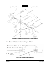
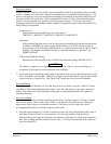
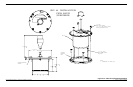
3. Strip back approximately 0.17 inches of insulation from each wire of the shielded cable (item 4)
and crimp a contact (item 2) to each conductor. It is the responsibility of the installer to
determine the proper length of insulation to be removed. Wire must be visible in the inspection
hole after crimping and the insulation must be 1/64 – 1/32 inches from the end of the contact as
shown in Figure B-17.
4. Insert newly crimped contacts and wires into the appropriate connector housing location as
specified by the installation wiring diagrams.
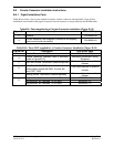
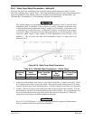
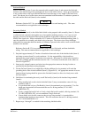
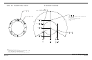
5. Cut the flat braid (item 6) to a length that, with the addition of a ring terminal, will reach the
grounding hole of the circular backshell (item 3) (Figure B-15). An appropriate amount of excess
length without looping should be given to the flat braid (item 6) to allow it to freely move with
the wire bundle.
6. Guidelines for terminating the newly cutoff flat braid(s) (item 6) with insulated ring terminals
(item 9):
• The grounding hole on the circular backshell (item 3) may accommodate a max of 4 ring
terminals (item 9).
• It is preferred that only two Flat Braid(s) (item 6) be terminated per ring terminal. Two flat
braids per ring terminal will necessitate the use of a #6 ring terminal, 14-16 AWG
(MS25036-107).
• If only a single flat braid is left or if only a single flat braid is needed, a #6 ring terminal, 18-
22 AWG (MS25036-102), can accommodate a single flat braid.
• If more braids exist for this connector than two per ring terminal, it is permissible to
terminate three braids per ring terminal. This will necessitate the use of a #6 ring terminal,
10-12 AWG (MS25036-111).
7. Repeat steps 1 through 7 as needed for the remaining shielded cables.