


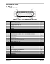
G3X Installation Manual – Pinouts Page A-3
190-01115-01 Revision A
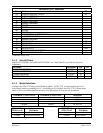
A.1.4 Serial Data
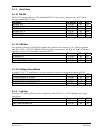
A.1.4.1 RS-232
The RS-232 outputs conform to EIA Standard RS-232C with an output voltage swing of 0-5V when
driving a standard RS-232 load.
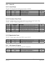
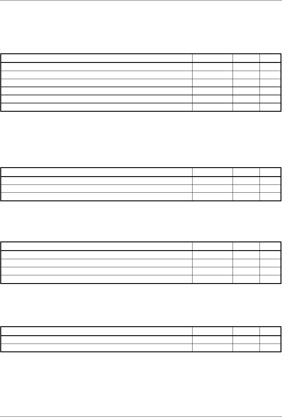
Pin Name Connector Pin I/O
RS-232 IN 1 P3701 47 In
RS-232 OUT 1 P3701 48 Out
RS-232 IN 2 P3701 14 In
RS-232 OUT 2 P3701 30 Out
RS-232 IN 3 P3701 29 In
RS-232 OUT 3 P3701 13 Out
A.1.4.2 CAN Bus
This data bus conforms to the BOSCH standard for Controller Area Network 2.0-B. This bus complies
with ISO 11898. CAN BUS TERMINATION should be connected to CAN BUS LO for the GDU that is
located at the end of the bus (farthest from the GSU 73).
Pin Name Connector Pin I/O
CAN BUS HI P3701 46 I/O
CAN BUS LO P3701 45 I/O
CAN BUS TERMINATION P3701 28 --
A.1.4.3 Configuration Module
In multiple GDU 37X installations, it is only necessary to connect a configuration module to PFD1.
Pin Name Connector Pin I/O
CONFIG MODULE CLOCK P3701 33 I/O
CONFIG MODULE DATA P3701 50 I/O
CONFIG MODULE POWER OUT P3701 17 Out
CONFIG MODULE GROUND P3701 49 --
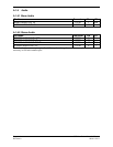
A.1.5 Lighting
The GDU 37X display and keys can be configured to track 28 VDC or 14 VDC lighting busses using
these inputs.
Pin Name Connector Pin I/O
14V LIGHTING BUS HI P3701 43 In
28V LIGHTING BUS HI P3701 26 In