


Page B-4 G3X Installation Manual – Appendix B
Revision A 190-01115-01
NOTES
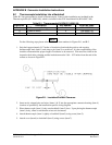
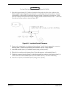
For the following steps please refer to Figures B-3 & B-4.
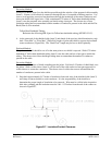
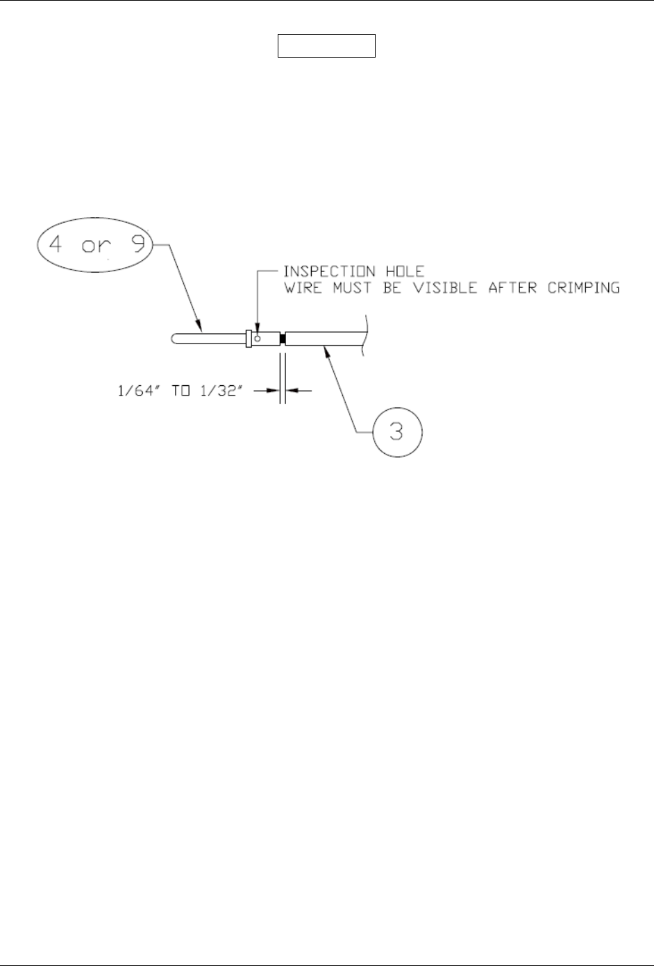
1. Strip back approximately 0.17 inches of insulation from each wire of the four conductor wire
harness (item 3) and crimp either a pin (item 4) or a socket (item 9) to each conductor. It is the
responsibility of the installer to determine the proper length of insulation to be removed. Wire
must be visible in the inspection hole after crimping and the insulation must be 1/64 – 1/32 inches
from the end of the contact as shown in Figure B-3.
Figure B-3. Insulation/Contact Clearance
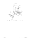
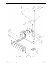
2. Insert newly crimped pins (or sockets) and wires (items 3 and 4) into the appropriate connector
housing (item 5) location as specified by the installation specific wiring diagram.
3. Attach the module (item 1) to backshell (item 6) using screw (item 10).
4. Plug the four conductor wire harness (item 3) into the connector on the module (item 1).
5. Orient the connector housing (item 5) so that the inserted four conductor wire harness (item 3) is
on the same side of the backshell (item 6) as the module (item 1)—as shown in drawing.
6. Attach cover (item 7) to backshell (item 6) using screws (item 8).