


Page 3-6 G3X Installation Manual – GMU 44
Revision A 190-01115-01
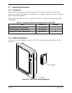
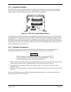
3.8 Mounting Instructions
After evaluation of the mounting location has been completed and ensuring that requirements are met,
assemble the GMU 44 mounting plate kits according to the dimensions given in Appendix C. Install the
unit assemblies.
Mount the GMU 44 to its mounting plate, taking care to tighten the mounting screws firmly. Use of non-
magnetic tools (e.g. beryllium copper or titanium) is recommended when installing or servicing the
GMU 44. Do not
use a screwdriver that contains a magnet when installing or servicing the GMU 44.
The metal components in the GMU 44's connector may slightly affect the magnetic field sensed by the
GMU 44. Place the connector at least 2 inches from the body of the GMU 44 to minimize this effect.
After attaching the GMU 44's connector to its mate in the aircraft wiring, secure the connector in place
using good installation practices. This will ensure that any remaining magnetic effect can be
compensated for using Calibration Procedure C: Magnetometer Calibration (Section 9.3.3).
NOTE
If the GMU 44 is ever removed, the anti-rotation properties of the
mounting screws must be restored. This may be done by replacing the
screws with new Garmin PN 211-60037-08. If original screws must be
re-used, coat screw threads with Loctite 242 (blue) thread-locking
compound, Garmin PN 291-00023-02, or equivalent. Important:
Mounting screws must be brass.
3.9 Maintenance
Maintenance of the GMU 44 is ‘on condition’ only. Periodic maintenance of the GMU 44 is not required.