


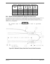
Page B-18 G3X Installation Manual – Appendix B
Revision A 190-01115-01
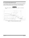
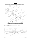
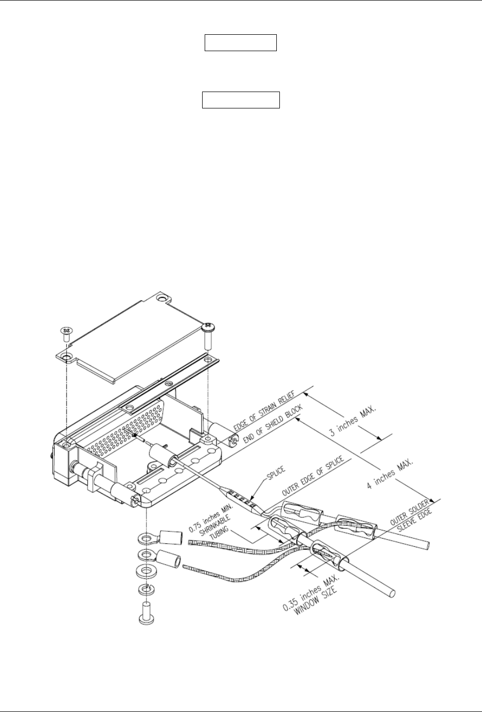
B.3.10 Splicing Signal Wires
NOTES
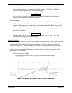
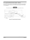
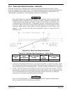
Figure B-14 illustrates that a splice must be made within a 3 inch window from outside
the edge of clamp to the end of the 3 inch max mark.
WARNING
Keep the splice out of the backshell for pin extraction, and outside of the strain relief to
avoid preloading.
Figure B-14 shows a two wire splice, but a maximum of three wires can be spliced. If a third wire is
spliced, it is located out front of splice along with signal wire going to pin.
Splice part numbers:
Raychem D-436-36/37/38
MIL Spec MIL-S-81824/1
This technique may be used with shield termination methods: A.1, A.2, B.1, B.2, C.1 and C.2.
Figure B-14. D-Sub Spliced Signal Wire illustration