


G3X Installation Manual – Appendix B Page B-17
190-01115-01 Revision A
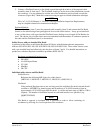
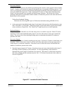
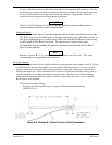
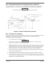
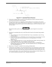
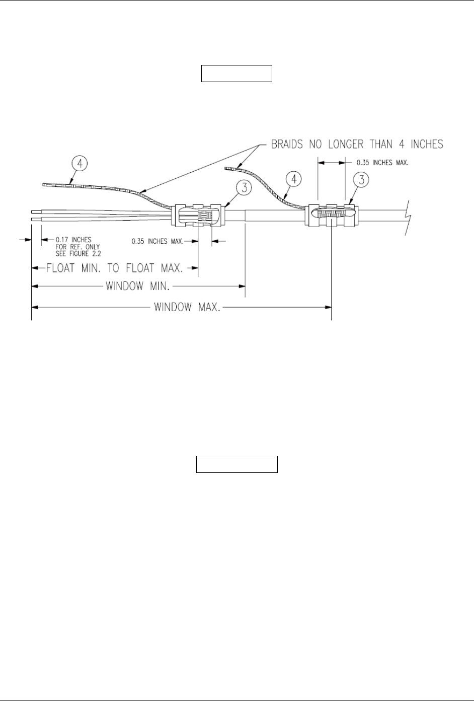
B.3.8 Double-Shield Termination Technique (Quick Term) - Method C.2
In addition to method C.1, described previously, another suitable method for double-shielding wires is
presented in Figure B-13. All restrictions set forth for Method C.1 (Table B-8) are still applicable.
NOTE
The maximum length of the braids should be approximately 4 inches.
Figure B-13. Method C.2 Double-Shield Termination
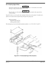
B.3.9 ID Program Pins (Strapping)
ID Program Pins provide a ground reference used by the hardware as a means of configuration for system
identification. The following instructions will illustrate how this ground strapping should be
accomplished with the Jackscrew Backshell:
1. Cut a 4 inch length of 22 AWG insulated wire.
WARNING
Flat Braid is not permitted for this purpose. Use only insulated wire to avoid inadvertent
ground issues that could occur from exposed conductors.
2. Strip back approximately 0.17 inches of insulation and crimp a contact (item 6) to the 4” length of
22 AWG insulated wire. It is the responsibility of the installer to determine the proper length of
insulation to be removed. Wire must be visible in the inspection hole after crimping and the
insulation must be 1/64 – 1/32 inches from the end of the contact as shown in Figure B-7.
3. Insert newly crimped pins and wires into the appropriate connector housing location as specified
by the installation wiring diagrams.
4. At the end opposite the pin on the 22 AWG insulated wire strip back 0.2 inches of insulation.
5. Terminate this end via the ring terminals with the other Flat Braid per Steps 8 and 11 pertaining
to shield termination. If this ground strap is only wire
to terminate, attach a Ring terminal, #8,
insulated, 18-22 AWG (MS25036-149).