


G3X Installation Manual – Appendix B Page B-23
190-01115-01 Revision A
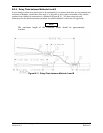
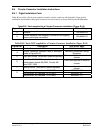
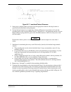
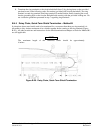
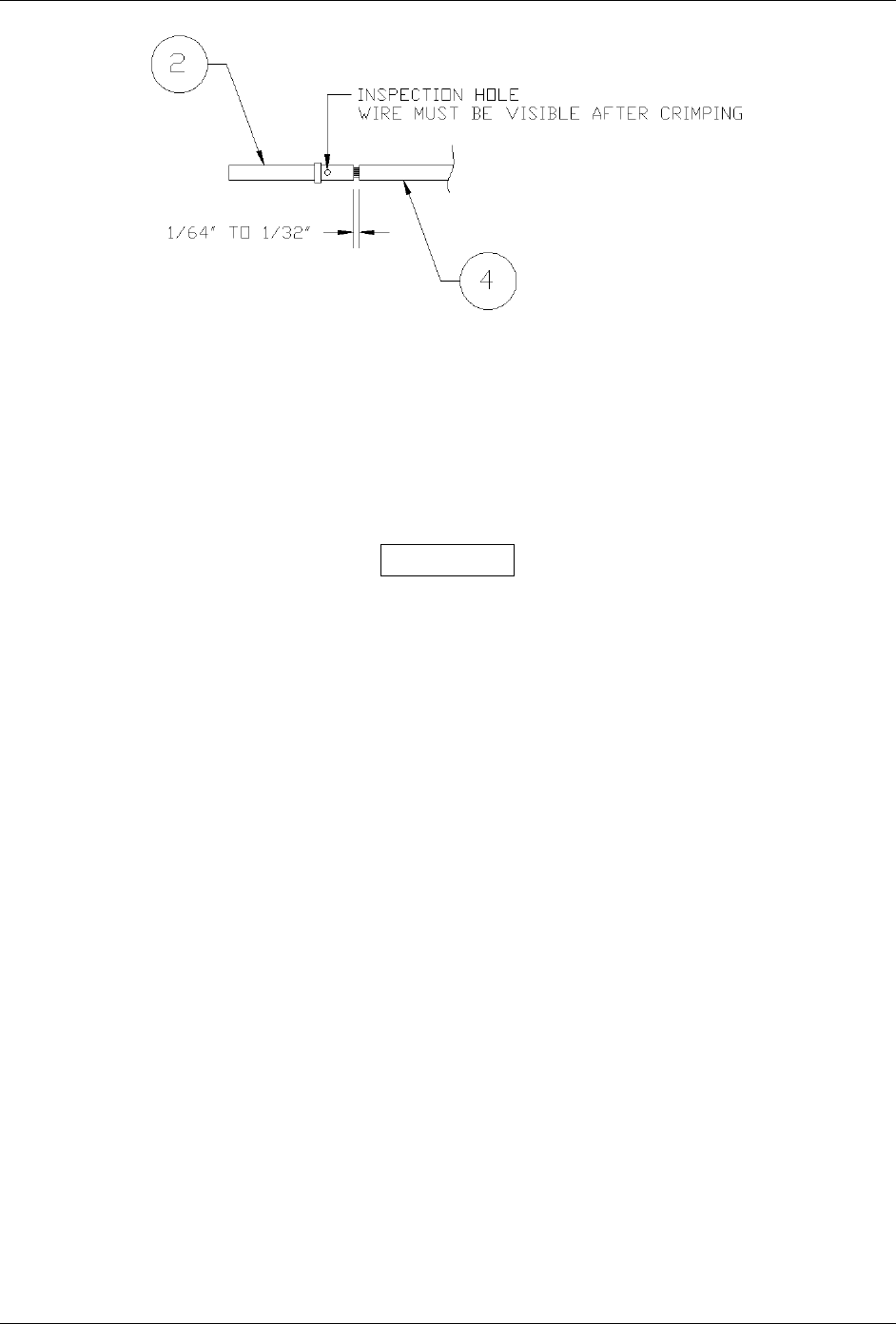
Figure B-17. Insulation/Contact Clearance
5. Insert newly crimped contacts and wires into the appropriate connector housing location as
specified by the installation wiring diagrams.
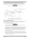
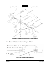
6. Cut the flat braid (item 6) to a length that, with the addition of a ring terminal, will reach the
grounding hole of the circular backshell (item 3) (Figure B-15). An appropriate amount of excess
length without looping should be given to the flat braid (item 6) to allow it to freely move with
the wire bundle.
NOTE
Position the window splice to accommodate a flat braid (item 6) length of no more than 4
inches.
7. Guidelines for terminating the newly cutoff flat braid(s) (item 6) with insulated ring terminals
(item 9):
• The grounding hole on the circular backshell (item 3) may accommodate a max of 4 ring
terminals (item 9).
• It is preferred that only two Flat Braid(s) (item 6) be terminated per ring terminal. Two flat
braids per ring terminal will necessitate the use of a #6 ring terminal, 14-16 AWG
(MS25036-107).
• If only a single flat braid is left or if only a single flat braid is needed, a #6 ring terminal, 18-
22 AWG (MS25036-102), can accommodate a single flat braid.
• If more braids exist for this connector than two per ring terminal, it is permissible to
terminate three braids per ring terminal. This will necessitate the use of a #6 ring terminal,
10-12 AWG (MS25036-111).
8. Repeat steps 1 through 7 as needed for the remaining shielded cables.
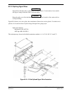
9. Terminate the ring terminals to the circular backshell (item 3) by placing items on the provided
pan head screw in the following order: flat washer (provided with circular backshell), first ring
terminal, second ring terminal, third ring terminal (if needed) before finally inserting the screw
into the grounding hole on the circular backshell and securing with the provided locking nut. Do
not violate the guidelines presented in step 7 regarding ring terminals.