


Page A-12 G3X Installation Manual – Pinouts
Revision A 190-01115-01
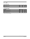
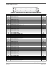
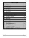
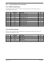
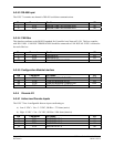
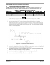
A.3.5.3 RS-485 Input
The GSU 73 contains one channel of RS-485 serial data communications.
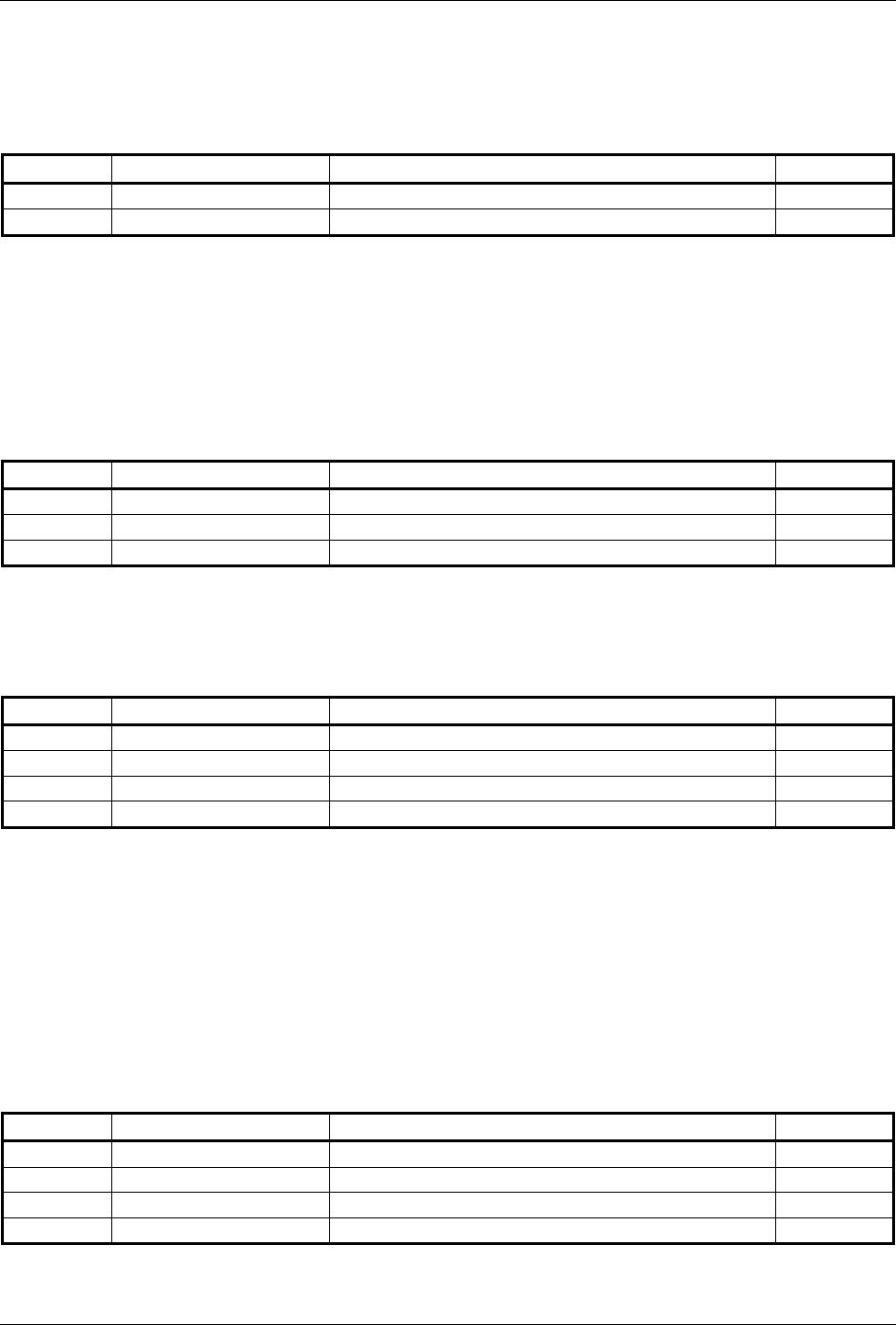
Pin Connector Pin Name I/O
1 P731 MAGNETOMETER RS-485 IN B IN
2 P731 MAGNETOMETER RS-485 IN A IN
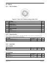
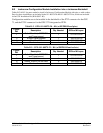
A.3.5.4 CAN Bus
This data bus conforms to the BOSCH standard for Controller Area Network 2.0-B. This bus complies
with ISO 11898. CAN BUS TERMINATION should be connected to CAN BUS LO if GSU is located at
the end of the bus.
Pin Connector Pin Name I/O
7 P731 CAN BUS HI I/O
8 P731 CAN BUS LO I/O
29 P731 CAN BUS TERMINATION --
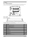
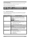
A.3.5.5 Configuration Module Interface
Pin Connector Pin Name I/O
20 P732 CONFIG MODULE CLOCK OUT
39 P732 CONFIG MODULE DATA I/O
59 P732 CONFIG MODULE POWER OUT OUT
78 P732 CONFIG MODULE GROUND --
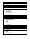
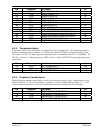
A.3.6 Discrete I/O
A.3.6.1 Active Low Discrete Inputs
The GSU 73 has 4 configurable discrete inputs conforming to:
a) Low: 0 VDC < Vin < 3.5 VDC, OR Rin < 375 ohms (active)
b) High: 8 VDC < Vin < 36 VDC, OR Rin> 100k ohms (inactive)
Pin Connector Pin Name I/O
9 P731 DISCRETE IN* 1 IN
10 P731 DISCRETE IN* 2 IN
11 P731 DISCRETE IN* 3 IN
12 P731 DISCRETE IN* 4 IN
* Indicates Active Low