


G3X Installation Manual – Pinouts Page A-15
190-01115-01 Revision A
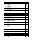
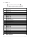
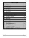
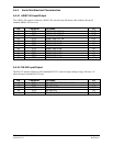
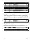
Pin Connector Pin Name I/O
47 P732 ANALOG IN 22 HI
IN
67 P732 ANALOG IN 22 LO
IN
28 P732 ANALOG IN 23 HI
IN
8 P732 ANALOG IN 23 LO
IN
27 P732 ANALOG IN 24 HI
IN
7 P732 ANALOG IN 24 LO
IN
66 P732 ANALOG IN 25 HI
IN
46 P732 ANALOG IN 25 LO
IN
70 P732 ANALOG/CURRENT MONITOR IN 1 HI
IN
50 P732 ANALOG/CURRENT MONITOR IN 1 LO
IN
48 P732 ANALOG/CURRENT MONITOR IN 2 HI
IN
68 P732 ANALOG/CURRENT MONITOR IN 2 LO
IN
10 P732 THERMOCOUPLE REF IN HI
IN
9 P732 THERMOCOUPLE REF IN LO
IN
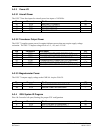
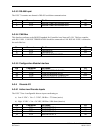
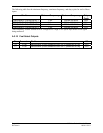
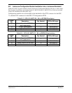
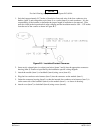
A.3.8 Temperature Inputs
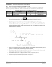
Temperature input is used for Outside Air Temperature (OAT) computations. The temperature input is a
three-wire temperature probe interface. OAT Power Out and OAT High are connected internally at the
OAT probe. A GTP 59 or other supported temperature probe is required for the GSU 73 installation. The
GTP 59 is a Resistive Temperature Device (RTD). Refer to Figure C-1?????? for the temperature probe
interconnect.
Pin Connector Pin Name I/O
15 P732 OAT PROBE IN HI IN
16 P732 OAT PROBE POWER OUT OUT
35 P732 OAT PROBE IN LO IN
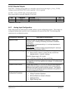
A.3.9 Frequency Counter Inputs
Digital signals are updated to the display at a rate of 10 times per second (10 Hz). Digital inputs are low
when the signal is 2 Vdc or the resistance to ground is 375 , and high when the signal is > 3.5 Vdc
or the resistance to ground is > 100 k . Digital inputs can also be configured as discrete inputs.
Pin Connector Pin Name I/O
17 P732 FREQUENCY COUNTER IN* 1 IN
19 P732 FREQUENCY COUNTER IN* 2 IN
36 P732 FREQUENCY COUNTER IN* 3 IN
38 P732 FREQUENCY COUNTER IN* 4 IN
* Indicates Active Low