


G3X Installation Manual – GMU 44 Page 3-3
190-01115-01 Revision A
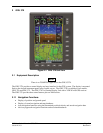
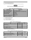
3.5 Installation Requirements
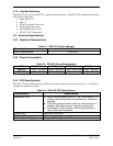
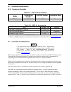
3.5.1 Equipment Available
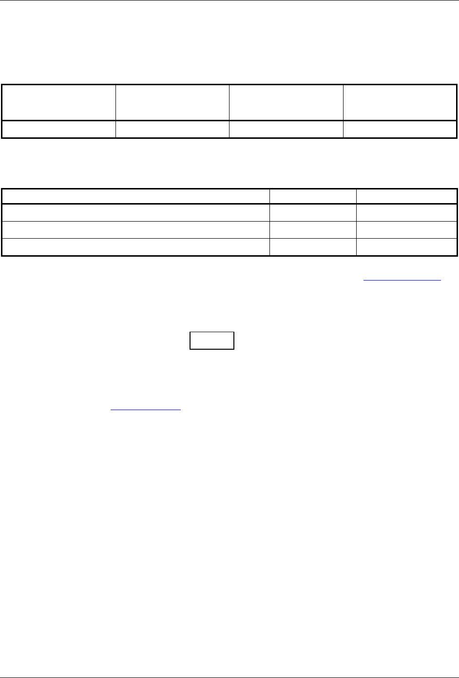
Table 3-5. GMU 44 Part Numbers
Model
Catalog Part
Number
Unit Part Number Installation Rack
GMU 44 010-00296-10* 011-00870-10 No
*Included in G3X LRU Kit (K10-00016-00)
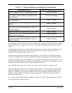
Table 3-6. GMU 44 Accessories
Item Garmin P/N Quantity
Sub Assy, Connector Kit, GMU 44 011-00871-00** 1
GMU 44 Universal Mount*** 011-01779-01 1 (optional)
Installation Rack, GMU 44 115-00481-10** 1
**Included in G3X Installation Kit (K10-00017-00)
***Refer to AHRS Magnetometer Installation Considerations (190-01051-00) from www.garmin.com
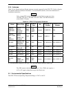
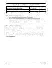
3.6 Installation Considerations
NOTE
If the requirements listed in Table 3-7 cannot be met, a magnetometer
interference test must be performed to ensure proper operation of the
G3X system. Refer to the AHRS/Magnetometer Installation
Considerations document (190-01051-00) available from the Garmin
website (
www.garmin.com).
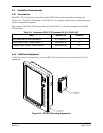
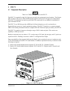
The following guidelines describe proper mechanical installation of the Garmin GMU 44 Magnetometer.
The guidelines include requirements for proper location selection in the aircraft, requirements for
supporting structure and mechanical alignment and restriction on nearby equipment.
Fabrication of a wiring harness is required. Sound mechanical and electrical methods and practices are
required for installation of the GMU 44. Refer to Section 1.6 for wiring considerations and to Appendix
A for pinouts.
The instructions needed to assemble the circular connector are located in Appendix B.
The GMU 44 is an extremely sensitive three-axis magnetic sensor. It is more sensitive to nearby
magnetic disturbances than a flux gate magnetometer. For this reason, when choosing a mounting
location for the GMU 44, observe the following distances from objects or devices that can disturb the
magnetic field. Table 3-7 specifies required distances from magnetic disturbances for GMU 44 location.