


Page 4-4 G3X Installation Manual – GSU 73
Revision A 190-01115-01
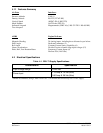
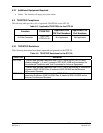
Table 4-5. Contents of P732 Connector Kit (011-01818-01)**
Item Garmin P/N Quantity
Sub-Assy,Backshell w/Hdw,Jackscrew 011-01855-04 1
Connector ,Hi Dens, D-Sub, Mil Crimp 78ck 330-00185-78 1
Contact Pin, Mil Crimp, Size 22D 336-00021-00 30
**Included in G3X Installation Kit (K10-00017-00)
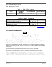
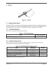
4.4.2 Additional Equipment Required
• Cables: The installer will fabricate and supply all system cables.
• Hardware: #10-32 pan or hex head screw (4 ea.) and #10-32 self-locking nut (4 ea)
• Air hoses and fittings to connect pitot and static air to the GSU 73. The GSU 73 has a female
1/8-27 ANPT fitting for each pitot and static port. Use appropriate aircraft fittings to connect to
pitot and static system lines.
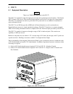
4.5 Installation Considerations
Fabrication of a wiring harness is required. Sound mechanical and electrical methods and practices
should be used for installation of the GSU 73. Refer to Section 1.6 for wiring considerations, and to
Appendix A for pinouts.
Connector kits include backshell assemblies. The backshell assembly houses the configuration module
(P732 only) and a thermocouple reference junction (if applicable). Garmin’s backshell connectors give
the installer the ability to quickly and easily terminate shield grounds at the backshell housing. The
instructions needed to install the Jackscrew Backshell, Configuration Module, and Thermocouple are
located in Appendix B.