


G3X Installation Manual – Antennas Page 6-23
190-01115-01 Revision A
6.6 Non-Structural Mount Installation
This section provides installation examples and considerations for non-structural mounting of teardrop
and ARINC 743 footprint antennas. Typical installations may be below a non-metallic glareshield, under
the composite or fabric skin, or on an external, non-structural surface. Other non-structural installations
may exist, but are not presented in this manual.
6.6.1 Generic Non-structural Antenna Installation
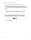
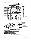
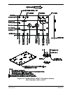
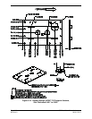
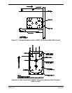
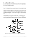
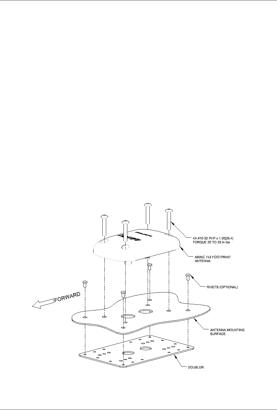
Figure 6-25 shows the generic non-structural installation for the ARINC 743 footprint (GA55A/GA 57X)
antenna. The teardrop footprint antennas (GA55, GA56 stud mount) can also be installed in this manner.
For mounting the teardrop style antenna (GA 55 or GA56), a doubler plate similar to Figure 6-4 or P/N
115-00846-10 can be used with the mounting surface to support the antenna. Rivets used to secure the
doubler plate to the mounting surface are optional in a non-structural installation. Screws, washers, and
locking nuts as shown in Appendix C are required to secure the Teardrop style antenna to the mounting
surface. Torque the locking nuts to 12-15 in-lbs, torque should be applied evenly across all mounting
studs.
A doubler plate similar to Figure 6-14, or P/N 115-00846-00 (ARINC 743 style) can be used with the
mounting surface to support the antenna. Rivets used to secure the doubler plate to the mounting surface
are optional in a non-structural installation. Locking nuts are required to secure the ARINC 743 antenna
(locking nuts installed on doubler). Torque the four supplied #10-32 stainless steel screws (Garmin P/N:
211-60212-20, MS51958-67, or equivalent) evenly across all mounting screws.
Figure 6-25. Generic Non-structural ARINC 743 Footprint Antenna Installation