


G3X Installation Manual – Post Installation Checkout and Calibration Procedures Page 8-23
190-01115-01 Revision A
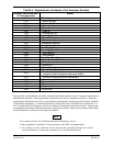
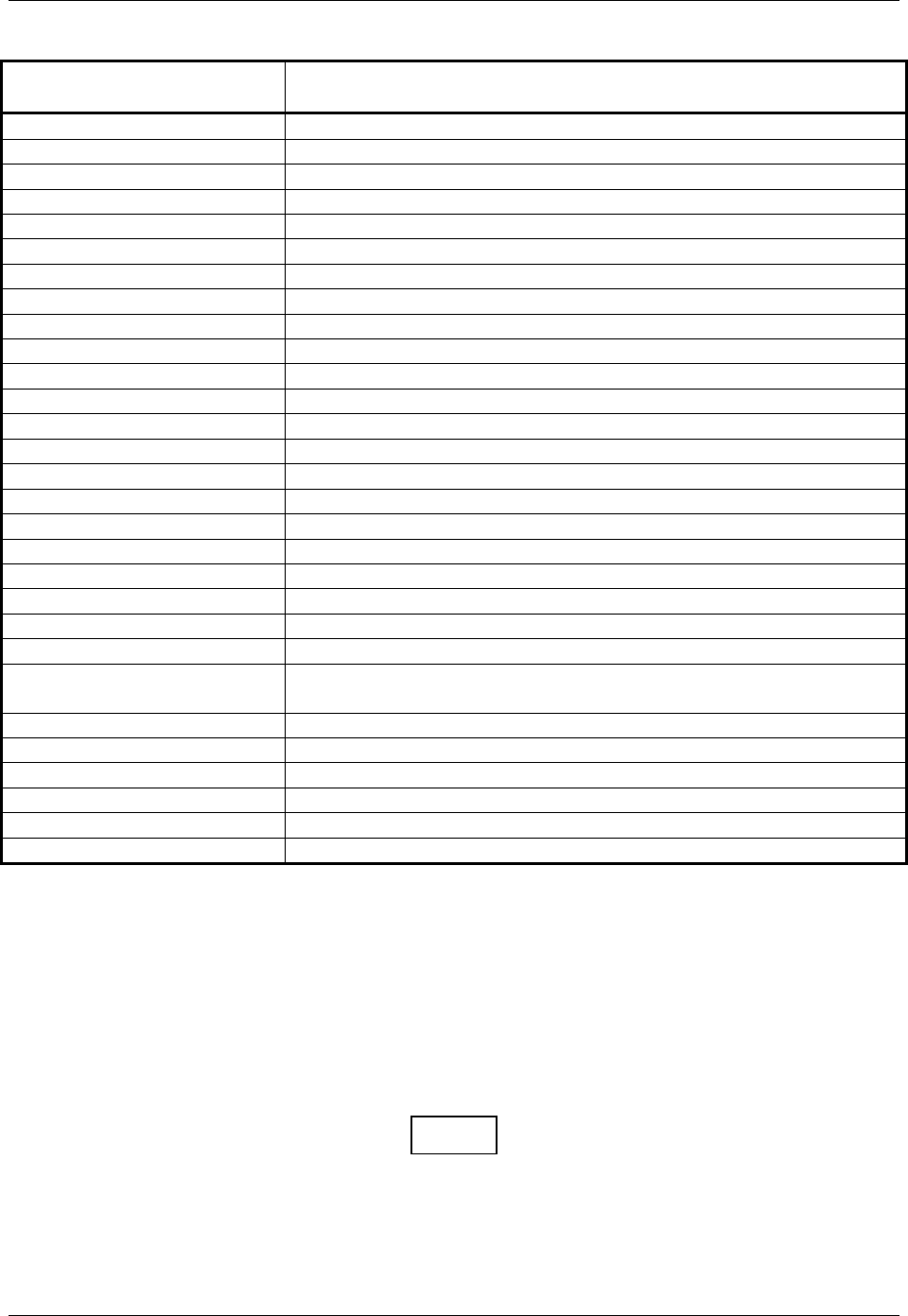
Table 8-4. Magnetometer Interference Test Sequence Example
Elapsed Time Since Start
of Test (min:secs)
Action
0:00 Test begins
0:10 Aileron full right
0:20 Aileron full left
0:30 Aileron level
0:40 Flaps down
0:50 Flaps up
1:00 Landing gear up
1:20 Landing gear down
1:40 Speed brake up
1:50 Speed brake down
2:00 Navigation lights on
2:10 Navigation lights off
2:20 Landing lights on
2:30 Landing lights off
2:40 Taxi lights on
2:50 Taxi lights off
3:00 Landing + Taxi lights on
3:10 Landing + Taxi lights off
3:20 Strobes on
3:30 Strobes off
3:40 Recognition lights on
3:50 Recognition lights off
4:00
Turn on all wing-tip lights simultaneously (typically will include
navigation lights, recognition lights and strobe)
4:10 Turn off all wing-tip lights simultaneously
4:20 Beacon on
4:30 Beacon off
4:40 Pitot heat on
4:50 Pitot heat off
5:00 End of test
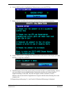
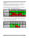
If the test fails, the installation should be considered unreliable until the source of magnetic interference is
identified and remedied. The magnetometer interference test must be repeated until passed. When the
magnetometer interference test fails, record the three magnetometer maximum deviation values and their
corresponding timestamps. A maximum deviation value greater than 5.0 milliGauss in either the X or Y
axes, or greater than 8.0 milligauss in the Z axis indicates a problem that must be resolved. Compare the
corresponding timestamps with the prepared test sequence to identify which action produced the problem.
Contact Garmin for assistance in resolving the problem.
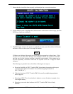
NOTE
Two common reasons for a failed magnetometer interference test are:
1) New equipment is installed in close proximity to the GMU 44 magnetometer.
2) An existing or new electronic device has become grounded through the aircraft
structure instead of via the proper ground wire in a twisted shielded pair.