


85
CHAPTER 7 TROUBLESHOOTING
7
7.3 Troubleshooting by Symptom
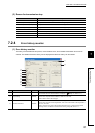
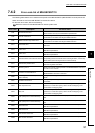
7.3.2 Items checked when data link cannot be performed throughout the system
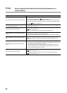
7.3.2 Items checked when data link cannot be performed
throughout the system
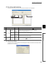
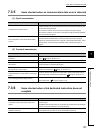
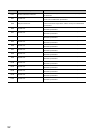
7.3.3 Items checked when data link is disabled by resetting or
powering off a station
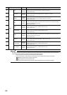
Check item Check procedure
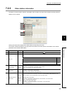
Check the communication status of each station by
performing network diagnostics using a peripheral.
• If an optical loop system is configured, check the line status with the loop test.
( Page 44, Section 4.4.1)
• Check the status of the CPU module and network module on the communication
error station.
• Check the status of the network module and cables with the self-loopback test and
station-to-station test. ( Page 40, Section 4.3.1)
• Check if the data link stop status is set to all stations.
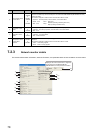
Are network parameters set to the remote master
station?
Read the network parameters from the CPU module on the remote master station,
and check if they are set correctly.
Are the switch settings of the network module
correct?
Set switches such as the network number setting switches, station number setting
switches, mode setting switch, and condition setting switch.
Is the “Monitoring time” setting correct?
Set the maximum value to the “Monitoring time” parameter, and check if data link is
performed properly.
Has the remote master station been down? Check the LED status of the MELSECNET/10 remote master module.
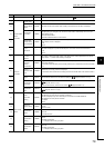
Check item Check procedure
Are the cables wired properly?
Check the wiring status with the loop test. ( Page 44, Section 4.4.1)
Are the cables connected properly?
Check the status of each station, and identify the error location (whether the entire
system is faulty or a cirtain station is faulty).
Are the switch settings of the network module
correct?
• Check if the station number setting switches, mode setting switch, and condition
setting switch of the MELSECNET/10 remote I/O module are set within the range.
If the settings are out of the range, correct them.
• Check if the station number setting switches of the MELSECNET/H remote I/O
module is set within the range. If the setting is out of the range, correct it. Also,
check if the mode setting switch is set to "8".
Is the “Monitoring time” setting correct?
Set the maximum value to the “Monitoring time” parameter, and check if data link is
performed properly. Check if the following LED on the remote I/O station is on.
• MELSECNET/10 remote I/O station: TIME LED
• MELSECNET/H (MELSECNET/10 mode) remote I/O station: L ERR. LED