


110
SD5
Error common
information
Error common
information
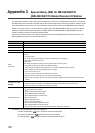
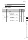
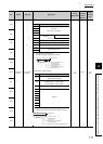
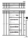
*4 Definitions of the base No. and slot No.
[Base No.]
This number indicates a base unit on which the CPU module is
mounted.
[Slot No.]
This number is used to identify the slot of each base unit and a
module mounted on the slot.
The "0" I/O slot (slot on the right of the CPU slot) on the main
base unit is defined as "Slot No. = 0".
The slot Nos. are assigned in sequence numbers in order of the
main base unit and then the first extension base unit to 7th
extension base unit.
When the number of slots on base units has been set in the I/O
assignment tab of the PLC Parameter dialog box, the slot Nos.
are assigned by the number of set slots.
*5 If FFFF
H
is stored in SD6 (I/O No.), this indicates that the I/O No.
cannot be identified due to an error such as overlap of an I/O No.
in the I/O assignment tab of the PLC Parameter dialog box. In
this case, identify the error location using SD5.
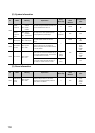
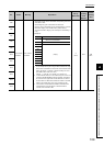
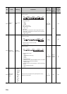
2) File name/drive name
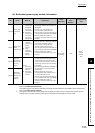
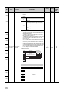
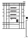
3) Time (value set)
S
(Error)
New
Rem
SD6
SD7
SD8
SD9
SD10
SD11
SD12
SD13
SD14
SD15
No. Name Meaning Explanation
Set by
(When Set)
Corres-
ponding
ACPU
D9
Corres-
ponding
CPU
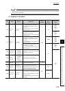
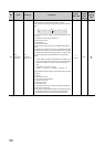
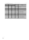
Base No. Definition
0
Indicates the main base unit where a CPU module
is mounted.
1 to 7
Indicates the extension base unit. The stage
number setting made by the stage number setting
connector on the extension base unit is the base
No.
• When stage number setting is extension 1: Base
No. = 1
• When stage number setting is extension 7: Base
No. = 7
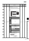
Number
SD5
SD6
SD7
SD8
SD9
SD10
SD11
SD12
SD13
SD14
SD15
Drive
B15toB8 to
Description
File name
(ASCII code: 8 characters)
Extension
*6
(ASCII code: 3 characters)
2E
H(.)
(Empty)
(Example)
File name =
ABCDEFGH.IJK
B7 B0
42H(B)
44
H(D)
46
H(F)
48
H(H)
49
H(I)
4B
H(K)
41
H(A)
43
H(C)
45
H(E)
47
H(G)
2E
H(.)
4A
H(J)
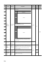
No. Description
SD5 Time: 1µs units (0 to 999µs)
SD6 Time: 1ms units (0 to 65535ms)
SD7
(Empty)
SD8
SD9
SD10
SD11
SD12
SD13
SD14
SD15