


124
*1 The "power supply 1" indicates the redundant power supply module mounted on the POWER 1 slot of the redundant
base unit (Q3RB/Q6RB/Q6WRB).
The "power supply 2" indicates the redundant power supply module mounted on the POWER 2 slot of the redundant
base unit (Q3RB/Q6RB/Q6WRB).
*2 This applies to modules with a serial number (first five digits) of "07032" or later. However, for the multiple CPU system
configuration, this applies to all CPU modules with a serial number (first five digits) of "07032" or later.
*3 This applies to modules with a serial number (first five digits) of "10042" or later.
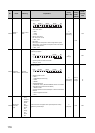
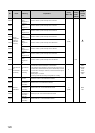
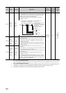
SD1781
Power
supply
failure
detection
Power
supply
failure
detection
status
• This register stores failure detection status of a redundant power supply
module (Q6RP) in the following bit pattern. (After a failure is detected on
a redundant power supply module, the bit corresponding to the failed
module turns to “0” upon turning off the module.)
• When the main base unit is not a redundant power main base unit
(Q3RB), “0” is stored.
• In a multiple CPU system, the status is stored only to CPU module No.1.
S
(Every END
processing)
New
Qn(H)
*2
QnPH
*2
QnPRH
Rem
QnU
*3
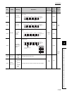
SD1782
Momentary
power
failure
detection
counter for
power
supply 1
*1
Momentary
power
failure
detection
count for
power
supply 1
• This register counts the number of times of momentary power failure of
the power supply 1/2.
• This register monitors the status of the power supply 1/2 mounted on a
redundant power main base unit (Q3RB) and counts the number of
momentary power failures.
The status of power supply 1/2 mounted on the extension base unit for
redundant power supply system and the redundant type extension base
unit is not monitored.
• When the CPU module starts, the counter of the power supply 1/2 is
cleared to “0”.
• If the input power to one of the redundant power supply modules is turned
off, the corresponding counter is cleared to “0”.
• The counter is incremented by one upon momentary power failure on the
power supply 1 or 2.
• When the main base unit is not a redundant power main base unit
(Q3RB), “0” is stored.
• In a multiple CPU system, the status is stored only to CPU module No.1.
• The counter repeats increment and decrement of the value; 032767-
327680. (The value is displayed within the range of 0 to 65535 on the
device monitor window of GX Developer.)
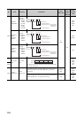
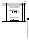
SD1783
Momentary
power
failure
detection
counter for
power
supply 2
*1
Momentary
power
failure
detection
count for
power
supply 2
No. Name Meaning Explanation
Set by
(When Set)
Corres-
ponding
ACPU
D9
Corres-
ponding
CPU
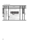
b0b7b15
to
to
toto
SD1781
One of the following values
is stored in each bit.
b1b8b9
Failure detection
status of the power
supply module 2
*1
Failure detection
status of the power
supply module 1
*1
0: Redundant power supply module
failure not detected/
No redundant power supply module
1: Redundant power supply module
failure detected
(detected only in a redundant
power supply module)
Main base unit
1st extension base unit
7th extension base unit
Main base unit
1st extension base unit
7th extension base unit