


79
CHAPTER 7 TROUBLESHOOTING
7
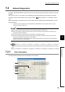
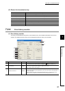
7.2 Network Diagnostics
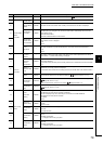
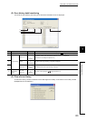
7.2.3 Network monitor details
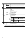
No. Item SB/SW Description
Network info.
The information same as "Host information" is displayed. ( Page 75, Section 7.2.1)
1)
Remote Master
Station
Information
Assign Remote
Master Station
SW0057 The station number (0) of the remote master station is displayed.
2)
Present
Remote Master
Station
SW0056 The station number of the station which actually controls the remote I/O station is displayed.
3)
Transmission
Information
SB0056
The type of the station which controls the remote I/O station is displayed.
The displayed type is changed to the remote sub-master station automatically when the remote
master station is down.
• Remote Master Station
• Remote Sub-Master Station Communication
4)
Remote Sub-
Master Station
Communication
SB0058
The cyclic transmission status (communication by the remote sub-master station) when the remote
master station is down is displayed.
•Yes
•None
5)
LX/LY
Allocations
The I/O assignment status is displayed.
The status is displayed only when GX Developer is connected to the remote master station.
•Yes
•None
6)
Data Link
Information
Total Number
of Linked
Stations
The number of stations (the total number of link stations set in network parameter for the remote
master station + 1 (remote master station)) is displayed.
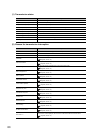
7)
Station of
Maximum
Normal
Transmission
SW005A
The greatest station number of the station where the baton pass (transient transmission) is normally
performed is displayed.
On the station where the baton pass is normally performed, the T.PASS LED of the network module
is on.
8)
Station of
Maximum Data
Link
SW005B
The greatest station number of the station where the data link (cyclic transmission and transient
transmission) is normally performed is displayed.
On the station where the data link is normally performed, the D.LINK LED of the network module is
on.
9)
Transmission
Status
SW0047
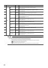
The transmission status of the host station is displayed. ( Page 80, Section 7.2.3 (1))
10)
Reason for
Transmission
Interruption
SW0048
The cause of the communication (transient transmission) failure of the host station is displayed.
( Page 80, Section 7.2 (2))
For the corrective action, refer to the error codes. ( Page 88, Section 7.4)
11)
Reason for
Transmission
Stop
SW0049
The cause of the data link (cyclic transmission) failure of the host station is displayed.
( Page 81, Section 7.2.3 (3))
12)
Status of Self
Station
Inteli-
Parameter
Setting
SW0054
The status of the intelligent function module parameters written to the MELSECNET/H
(MELSECNET/10 mode) remote I/O station is displayed.
This it
em is displayed only when GX Developer is connected to the MELSECNET/H
(MELSECNET/10 mode) remote I/O station.
• Available
•None
13)
Reserved
Station Setting
SB0064
The specification status of the reserved station is displayed.
• Exists
• Does not exist
14)
Transmission
Mode
SB0068
The status of the link scan is displayed.
•Normal
• Constant link scan
15)
Duplex
Transmission
Setting
SB0069
The specification status of the multiplex transmission is displayed.
•None
• Multiplex transmission
"----" is displayed for the bus type system.
16)
Duplex
Transmission
Status
SB006A
The status of the multiplex transmission is displayed.
•Normal
• Multiplex transmission
"----" is displayed for the bus type system.