


123
APPENDICES
A
Appendix 4 Special Register (SD) for MELSECNET/H (MELSECNET/10 Mode) Remote I/O Station
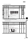
(5) I/O module verification
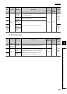
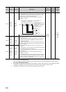
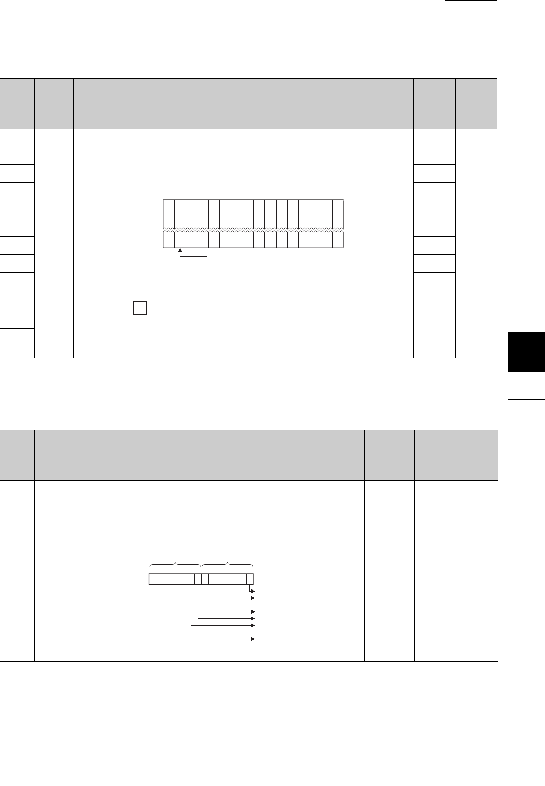
(6) Redundant power supply module information
The special register (SD1780 to SD1789) is valid only for redundant power supply systems. All bits are set to "0"
for single power supply systems.
No. Name Meaning Explanation
Set by
(When Set)
Corres-
ponding
ACPU
D9
Corres-
ponding
CPU
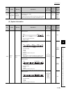
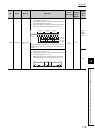
SD1400
I/O
module
verify
error
Bit pattern,
in units of 16
points,
indicating
the module
with an I/O
module
verify error
0: No
error
1: Error
• If the status of the I/O module changes from that obtained at power-on,
the module No. is stored in the following bit pattern (in units of 16 points).
(If the I/O numbers are set by parameter, the parameter-set numbers are
stored.)
• I/O module information is also detected.
• For a module whose number of I/O points exceeds 16 points, all bits
corresponding to I/O module numbers within the number of I/O points
occupied by the module (in units of 16 points) turn on.
When a 64-point module is mounted on the slot 0, b0 to b3 turn on
when an error is detected.
• The module No. is not cleared even when the I/O module goes back to
normal.
The number is cleared by clearing the error.
S
(Error)
D9116
QnA
Qn(H)
QnPH
QnPRH
QnU
Rem
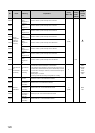
SD1401 D9117
SD1402 D9118
SD1403 D9119
SD1404 D9120
SD1405 D9121
SD1406 D9122
SD1407 D9123
SD1408
New
SD1409
to
SD1430
SD1431
No. Name Meaning Explanation
Set by
(When Set)
Corres-
ponding
ACPU
D9
Corres-
ponding
CPU
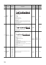
SD1780
Power
supply off
detection
status
Power
supply off
detection
status
• This register stores status of a redundant power supply module (Q6RP)
with input power off, in the following bit pattern.
• When the main base unit is not a redundant power main base unit
(Q3RB), “0” is stored.
• In a multiple CPU system, the status is stored only to CPU module No.1.
S
(Every END
processing)
New
Qn(H)
*2
QnPH
*2
QnPRH
Rem
QnU
*3
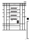
B15
14
13
12 11
1098765
4
3
21
0
000 000 0000000
SD1400
00 0 00000000
SD1401
00
0 0 0000 000
SD1431
0000
Indicates an I/O module verification error.
00
00
00
1
(
)
X Y
1FE0
1
( )
X Y
0
1
( )
X Y
190
Ex.
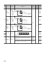
b0b7b15
to
to
toto
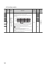
SD1780
b1b8b9
Input power supply
OFF detection status
of the power supply
module 2
*1
Input power supply
OFF detection status
of the power supply
module 1
*1
0: Input power supply ON status/
No redundant power supply module
1: Input power supply OFF status
Main base unit
1st extension base unit
7th extension base unit
Main base unit
1st extension base unit
7th extension base unit
One of the following values is
stored in each bit.