


40
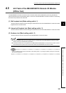
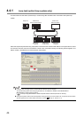
4.3.1 Self-loopback test
This test checks the internal circuits including the send/receive circuits of the MELSECNET/H remote I/O module
together with the connected cable.
Always connect a cable or terminating resistors when performing the self-loopback test. In addition, do not connect or
disconnect the cable or terminating resistors during the test. (The test completes with an error.)
If an error occurs, perform the following.
• For the QJ72LP25-25, QJ72LP25G, QJ72LP25GE replace the cable and perform the test again.
• For the QJ72BR15, replace the terminating resistors and perform the test again.
When the test completes with an error again, the possible cause is a hardware failure of the MELSECNET/H remote
I/O module. Please consult your local Mitsubishi representative.
Remark
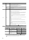
Check the test condition and error details with the following link special register areas.
• Baton pass status (host) (SW0047) 1F
H
: Offline test
• Cause of baton pass interruption (SW0048) 2
H
: Offline test
• Offline test execution item/faulty station (requesting side) (SW00AC) 7
H
: Self-loopback test
• Offline test result (requesting side) (SW00AD) 0: Normal, 1 and later: Error code
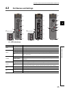
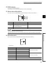
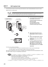
1. For the QJ72LP25-25, QJ72LP25G, and
QJ72LP25GE, connect the IN
connector and OUT connector by an
optical fiber cable.
For the QJ72BR15, connect
terminating resistors to both
connectors of the F-type connector.
2. Set the mode setting switch on the
MELSECNET/H remote I/O module to
"1".
3. Power on the target module. The self-
loopback test starts and the T.PASS
LED flashes.
4. The test is completed normally when
the T.PASS LED flashes 20 or more
times (approx. 10 seconds) and the
ERR. LED does not flash. When the
test completes with an error, the ERR.
LED flashes.
For QJ72LP25-25,
QJ72LP25G, QJ72LP25GE
(optical loop system)
For QJ72BR15
(coaxial bus system)
Connect
terminating
resistors.
Connect the
IN and OUT
connectors.
Flashing