


I
2
4
4
7
8
133
Number of online return stations setting function . . . 30
O
Online module change. . . . . . . . . . . . . . . . . . . . . . 22
Other station information . . . . . . . . . . . . . . . . . . . . 77
P
Parallel master system . . . . . . . . . . . . . . . . . . . . . 30
Parameter setting . . . . . . . . . . . . . . . . . . . . . . . . . 55
Parameter status of each station. . . . . . . . . . . . . . . 77
Peripheral . . . . . . . . . . . . . . . . . . . . . . . . . . . . . . 13
PLC parameter . . . . . . . . . . . . . . . . . . . . . . . . . . . 49
PLC RAS setting. . . . . . . . . . . . . . . . . . . . . . . . . . 50
Power supply module . . . . . . . . . . . . . . . . . . . . . . 20
Precautions for mounting intelligent function modules
. . . . . . . . . . . . . . . . . . . . . . . . . . . . . . . . . . . . . . 22
Precautions for replacing systems. . . . . . . . . . . . . . 53
Procedure before operation . . . . . . . . . . . . . . . . . . 33
Program example . . . . . . . . . . . . . . . . . . . . . . . . . 61
PSU operation status of each station extension . . . . 78
Q
Q series large type extension base unit (AnS series size)
(type requiring a power supply module)
. . . . . . . . . . 20
Q series large type extension base unit (AnS series size)
(type requiring no power supply module) . . . . . . . . . 20
Q series large type extension base unit
(type requiring a power supply module) . . . . . . . . . . 20
Q series large type extension base unit
(type requiring no power supply module)
. . . . . . . . . 20
Q series large type main base unit . . . . . . . . . . . . . 20
Q series large type main base unit
(AnS series size)
. . . . . . . . . . . . . . . . . . . . . . . . . . 20
R
RAS function . . . . . . . . . . . . . . . . . . . . . . . . . 26,31
RD . . . . . . . . . . . . . . . . . . . . . . . . . . . . . . . . . . . 35
Redundant type extension base unit . . . . . . . . . . . . 21
Reference manuals . . . . . . . . . . . . . . . . . . . . . . . . 16
Relay station . . . . . . . . . . . . . . . . . . . . . . . . . . . . 13
REM.. . . . . . . . . . . . . . . . . . . . . . . . . . . . . . . . . . 35
Remote I/O module . . . . . . . . . . . . . . . . . . . . . . . . 13
Remote I/O station . . . . . . . . . . . . . . . . . . . . . . . . 13
Remote master station. . . . . . . . . . . . . . . . . . . . . . 13
Remote master station information . . . . . . . . . . . . . 79
Remote password. . . . . . . . . . . . . . . . . . . . . . 31,51
Reserved station. . . . . . . . . . . . . . . . . . . . . . . . . . 13
Reserved station designation of each station . . . . . . 78
Reserved station function. . . . . . . . . . . . . . . . . . . . 29
RESET switch . . . . . . . . . . . . . . . . . . . . . . . . . . . 38
RUN . . . . . . . . . . . . . . . . . . . . . . . . . . . . . . . . . . 35
S
SD. . . . . . . . . . . . . . . . . . . . . . . . . . . . . . . . . . . . 35
Self-loopback test . . . . . . . . . . . . . . . . . . . . . . . . . 40
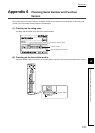
Serial number display . . . . . . . . . . . . . . . . . . . . . . 38
Setup confirmation test . . . . . . . . . . . . . . . . . . . . . 45
Slim type main base unit . . . . . . . . . . . . . . . . . . . . 20
Software package. . . . . . . . . . . . . . . . . . . . . . . . . 19
Special function module . . . . . . . . . . . . . . . . . . . . 14
Station number setting switches . . . . . . . . . . . . . . . 37
Station order check test
(only for optical loop system) . . . . . . . . . . . . . . . . . 46
Status of self station . . . . . . . . . . . . . . . . . . . . . . . 79
Supported version . . . . . . . . . . . . . . . . . . . . . . . . 19
System monitor for remote I/O stations . . . . . . . . . . 31
T
T.PASS . . . . . . . . . . . . . . . . . . . . . . . . . . . . . . . . 35
Transient transmission . . . . . . . . . . . . . . . . . . . . . 81
Transient transmission errors. . . . . . . . . . . . . . . . . 83
Transient transmission failure . . . . . . . . . . . . . . . . 87
Transient transmission function . . . . . . . . . . . . . . . 29
Transient transmission function
(irregular communications)
. . . . . . . . . . . . . . . . . . 31
Troubleshooting . . . . . . . . . . . . . . . . . . . . . . . . . . 70
Troubleshooting for each phenomenon . . . . . . . . . . 84
W
Web server module. . . . . . . . . . . . . . . . . . . . . . . . 21
When the D.LINK LED is off. . . . . . . . . . . . . . . . . . 74
When the ERR. LED is on or flashing . . . . . . . . . . . 73
When the L ERR. LED is on. . . . . . . . . . . . . . . . . . 73
When the REM. LED is off or flashing . . . . . . . . . . . 72
When the RUN LED does not turn on . . . . . . . . . . . 72
When the T.PASS LED is off or flashing . . . . . . . . . 74