


116
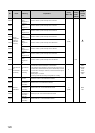
SD200
Status of
switch
Status of CPU
switch
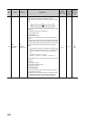
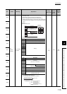
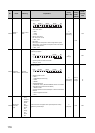
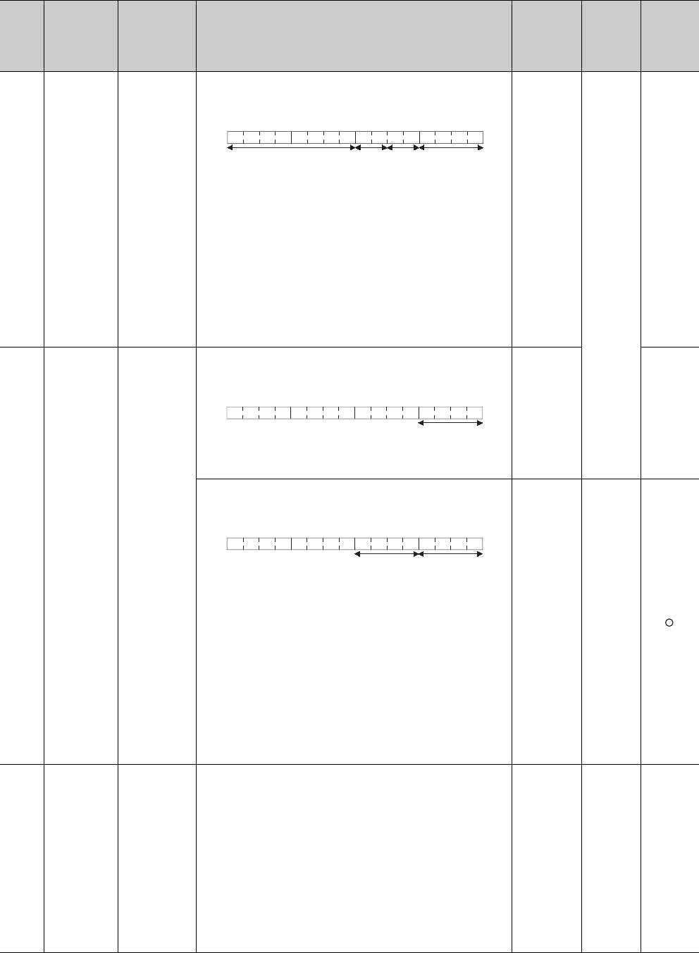
This register stores the status of the CPU module switches in the
following bit pattern.
1) CPU switch status
0: RUN
1: STOP
2: L.CLR
2) Memory card switch
B4: card A, B5: card B,
0: OFF, 1: ON.
3) DIP switch
B8 through B12 correspond to SW1 through SW5 of system
setting switch 1. B14 and B15 correspond to SW1 and SW2 of
system setting switch 2.
0: OFF, 1: ON.
S
(Every END
processing)
New
QnA
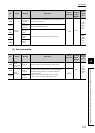
SD203
Operating
status of CPU
Operating
status of CPU
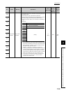
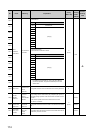
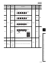
This register stores the operating status of the remote I/O module in
the following bit pattern.
1) Operating status of remote I/O module
Always 2: STOP
S
(Always)
Rem
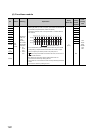
This register stores the operating status of the CPU module in the
following bit pattern.
1) Operating status of CPU
0: RUN
1: STEP-RUN (QnACPU only)
2: STOP
3: PAUSE
2) STOP/PAUSE cause
0: RUN/STOP switch ("RUN/STOP/RESET switch" for the Basic
model QCPU and Universal model QCPU)
1: Remote contact
2: Remote operation from GX Developer or serial communication
modules
3: Internal program instruction
4: Error
S
(Every END
processing)
D9015
format
change
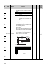
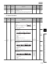
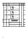
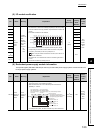
SD206
Device test
execution
type
0: No test
being
executed
1: During X
device
test
2: During Y
device
test
3: During
X/Y
device
test
A value is stored in this register when inputs/outputs are forcibly
registered by GX Developer.
S
(Request)
New Rem
No. Name Meaning Explanation
Set by
(When Set)
Corres-
ponding
ACPU
D9
Corres-
ponding
CPU
B15 B12B11 B8 B7 B4 B3 B0
1)2)
Empty
3)
B15 B4 B3 B0
1)
B15 B12B11 B8B7 B4 B3 B0
1)2)