


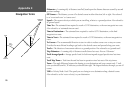
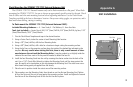

Mounting the GPSMAP 172/172C Unit
The GPSMAP 172/172C’s compact, waterproof case is suitable for mounting in exposed locations
or at the nav station. The unit comes with a single-knob tilt & swivel bracket that can be used for surface
or overhead mounting. When choosing a location for the display unit, make sure you consider the
following conditions:
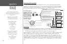
• There should be at least a 3” (7 cm) clearance behind the case to allow connection of the
antenna (external antenna only), power/data cables.
• The mounting surface should be heavy enough to support the unit and protect it from excessive
vibration and shock.
• For GPSMAP 172/172C unit’s with the built-in internal antenna, it should be mounted in a location
that has the clearest, most unobstructed view of the sky in all directions to ensure the best reception.
Avoid mounting the unit where it is blocked by the boat’s superstructure, a radar arch, or mast.
The temperature range for the GPSMAP 172/172C is 5°F to 158°F (-15°C to 55°C).
Extended exposure to temperatures exceeding this range (in storage or operating
conditions) may cause failure of the LCD screen. This type of failure and related conse
-
quences are NOT covered by the manufacturer’s limited warranty.
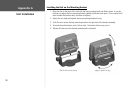
To swivel mount the GPSMAP 172/172C display:
Tools (not included) — Drill, Screwdriver (Phillips or Standard), three #8 (4mm) pan head machine
bolts with matching nuts and washers and a 5/32” (5mm) drill bit, OR three #8 pan head self-tap
-
ping screws and an appropriately-sized drill bit for drilling starter holes. Always wear safety goggles,
ear protection, and a dust mask when drilling, cutting or sanding.
1. Using the swivel base as a template, mark the location of the three holes that are used to secure
the bracket to the mounting surface.
2. If securing the base with machine bolts, drill three 5/32” (5mm) holes at the locations you marked.
OR, if securing the base with self-tapping screws, drill starter holes at the locations you marked.
Starter holes should generally be no deeper than half the screw length.
3. Secure the swivel base with three bolts or screws. DO NOT OVERTIGHTEN.
4. Place the rest of the mount over the swivel base and secure with the short knob.
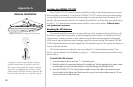
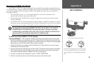
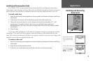
Secure the base and attach the mount
The swivel base is designed to be secured using a pan
head screw or machine bolt. If you use a screw with a
countersunk head, you risk damaging the Mounting
Base.
OK
89
Appendix G
Unit Installation