


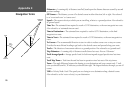
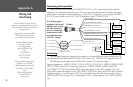
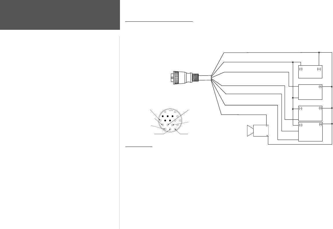
Connecting the Power/Data
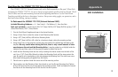
The power/data cable connects the GPSMAP 172/172C to a DC system and provides interface
capabilities for connecting external devices. The color code in the diagram below indicates the appro-
priate harness connections. Replacement fuse is a AGC/3AG 2.0 Amp fuse. For wiring the GPSMAP to
a GSD 20 Sonar Module, refer to the “GSD 20 Installation Guide” (190-00255-00).
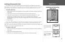
Interfacing
The following formats are supported for connection of external devices: Garmin proprietary GSD
20 Sonar Module and Differential GPS, NMEA 0183 version 3.01, RTCM SC-104 input (version 2.0).
The following are the sentences for
NMEA 0183, version 3.01 and later output:
Approved sentences— GPBWC, GPRMC, GPGGA, GPGSA, GPGSV, GPGLL, GPBOD, GPRMB, GPRTE,
GPVTG, GPWPL and GPXTE. Proprietary sentences— PGRME, PGRMM, PGRMZ, and PSLIB.
The GPSMAP 172/172C also includes NMEA input with support for the WPL sentence, DSC, and
sonar NMEA input with support for the DPT (Depth), MTW (Water Temp) and VHW (Water Speed &
Heading) sentences. If connecting to COM2 for sonar NMEA input, the unit interface must be set to
NMEA In/NMEA Out (see page 72). If connecting to COM1, the unit must be set to NMEA In/NMEA
Out.
Documentation concerning NMEA
&RTCM formats and sentences
are available for purchase from:
National Marine Electronics
Association (NMEA)
Seven Riggs Avenue
Severna Park, MD 21146
U.S.A.
410-975-9425
410-975-9450 FAX
www.nmea.org
Radio Technical Commission For
Maritime Services (RTCM)
1800 Diagonal Road, Suite 600
Alexandria, VA 22314-2480
U.S.A.
703-684-4481 (Info Only)
703-836-4229 FAX
www.rtcm.org
You can download a copy of Garmin's
proprietary communication protocol from the
Help and Support section of our web site at
www.garmin.com.
(red) 10-35vDC
(black)Ground(Power andData)
(blue)NMEAOUT(Com1TX)
(brown)NMEAIN(Com1RX)
(white)RTCM/NMEAIN(Com2RX)
(green)NMEAOUT(Com2TX)
(yellow)AlarmLow
NMEA
Devicewith
SonarOutput
TXD+
AlarmRelay
100mamax
coilcurrent
GSD20,
Beacon
Receiveror
DSCVHF
Autopilot/
NMEADevice
DC�
PowerSource
RXD+
RXD-
RX+
TX+
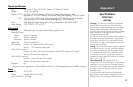
To Unit
Pin 16 - Brown (RX COM 1)
Pin 17 - Blue (TX COM 1)
Pin 13 - White (RX COM 2)
Pin 14 - Green (TX COM 2)
Pin 11
- Yellow (Alarm)
Pin 15 - Red (DC Positive
)
Pin 18 - Black (Ground)
(Cable End View)
Note: During a typical
installation, only the Red
and Black wires are used.
The other wires do not
have to be connected for
normal operation of the
unit. Replacement fuse:
AGC/3AG - 2.0 Amp
92
Appendix G
Wiring and
Interfacing