


including the range, bearing, speed, GPS heading, nearest
approach, and time to nearest approach. MARPA indicates the
status of each tagged object (acquiring, lost, tracking, or
dangerous), and the chartplotter can sound a collision alarm if
the object enters your safe zone.
MARPA Targeting Symbols
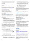
Acquiring a target. Concentric, dashed green rings radiate from
the target while the radar is locking onto it.
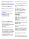
Target has been acquired. A solid green ring indicates the
location of a target that the radar has locked onto. A dashed
green line attached to the circle indicates the projected course
over ground or the GPS heading of the target.
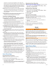
Dangerous target is in range. A red ring flashes from the target
while an alarm sounds and a message banner appears. After
the alarm has been acknowledged, a solid red dot with a dashed
red line attached to it indicates the location and the projected
course over ground or the GPS heading of the target. If the safe-
zone collision alarm has been set to Off, the target flashes, but
the audible alarm does not sound and the alarm banner does
not appear.
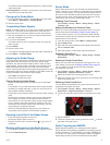
Target has been lost. A solid green ring with an X through it
indicates that the radar could not lock onto the target.
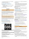
Closest point of approach and time to closest point of approach
to a dangerous target.
Assigning a MARPA Tag to an Object
Before you can use MARPA, you must have a heading sensor
connected and an active GPS signal. The heading sensor must
provide the NMEA 2000 parameter group number (PGN)
127250 or the NMEA 0183 HDM or HDG output sentence.
1
From the Harbor, Offshore, or Cruising Radar screen, select
an object or location.
2
Select Acquire Target > MARPA Target.
Viewing Information about a MARPA-tagged Object
You can view the range, bearing, speed, and other information
about a MARPA-tagged object.
1
From a radar screen, select a targeted object.
2
Select MARPA Target.
Removing a MARPA Tag from a Targeted Object
1
From the Radar screen, select a MARPA target.
2
Select MARPA Target > Remove.
Viewing a List of AIS and MARPA Threats
From any Radar screen or the Radar overlay, you can view and
customize the appearance of a list of AIS and MARPA threats.
1
From a Radar screen, select Menu > Other Vessels > List >
Show.
2
Select the type of threats to include in the list.
Showing AIS Vessels on the Radar Screen
AIS requires the use of an external AIS device and active
transponder signals from other vessels.
You can configure how other vessels appear on the Radar
screen. If any setting (except the AIS display range) is
configured for one radar mode, the setting is applied to every
other radar mode. The details and projected heading settings
configured for one radar mode are applied to every other radar
mode and to the Radar overlay.
1
From a Radar screen or the Radar overlay, select Menu >
Other Vessels > Display Setup.
2
Select an option:
• To indicate the distance from your location within which
AIS vessels appear, select Display Range, and select a
distance.
• To show details about AIS-activated vessels, select
Details > Show.
• To set the projected heading time for AIS-activated
vessels, select Proj. Heading, and enter the time.
• To show the tracks of AIS vessels, select Trails, and
select the length of the track that appears.
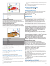
VRM and EBL
The variable range marker (VRM) and the electronic bearing line
(EBL) measure the distance and bearing from your boat to a
target object. On the Radar screen, the VRM appears as a circle
that is centered on the present location of your boat, and the
EBL appears as a line that begins at the present location of your
boat and intersects the VRM. The point of intersection is the
target of the VRM and the EBL.
Showing the VRM and the EBL
The VRM and the EBL configured for one mode are applied to
other radar modes.
NOTE: The VRM and the EBL cannot be changed in sentry
mode.
From a radar screen, select Menu > Show VRM/EBL.
Adjusting the VRM and the EBL
Before you can adjust the VRM and the EBL, you must show
them on the Radar screen (Showing the VRM and the EBL,
page 22).
You can adjust the diameter of the VRM and the angle of the
EBL, which moves the intersection point of the VRM and the
EBL. The VRM and the EBL configured for one mode are
applied to all other radar modes.
1
From a Radar screen, select a new location for the
intersection point of the VRM and the EBL.
2
Select Drop VRM/EBL.
3
Select Stop Pointing.
Measuring the Range and Bearing to a Target Object
Before you can adjust the VRM and the EBL, you must show
them on the Radar screen (Showing the VRM and the EBL,
page 22).
1
From a Radar screen, select the target location.
2
Select Measure Distance.
The range and the bearing to the target location appear in the
upper-left corner of the screen.
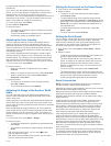
Radar Overlay
When you connect your chartplotter to an optional Garmin
marine radar, you can use the Radar overlay to overlay radar
information on the Navigation chart or on the Fishing chart.
The Radar overlay superimposes radar information on the
Navigation chart or the Fishing chart. Data appears on the
Radar overlay based on the most recently used radar mode
(such as Harbor, Offshore, or Sentry), and all settings
configurations applied to the Radar overlay are also applied to
the last-used radar mode. For example, if you use Harbor mode
and then you switch to the Radar overlay, the Radar overlay
would show Harbor mode radar data. If you changed the gain
setting using the Radar overlay menu, the gain setting for
Harbor mode would change automatically.
Radar Overlay and Chart Data Alignment
When using the Radar overlay, the chartplotter aligns radar data
with chart data based on the boat heading, which is based by
default on data from a magnetic heading sensor connected
using a NMEA 0183 or NMEA 2000 network. If a heading sensor
is not available, the boat heading is based on GPS tracking
data.
GPS tracking data indicates the direction in which the boat is
moving, not the direction in which the boat is pointing. If the boat
is drifting backward or sideways due to a current or wind, the
Radar overlay may not perfectly align with the chart data. This
22 Radar