Daniel 3812 Liquid Ultrasonic Flow Meter Installation Manual Section 4: Configuration
3-9000-765 Rev D March 2013
Using AMS Device Manager to configure the meter 85
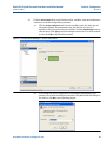
page. Navigate back to the Manual Setup for the changes to be reflected in other
Manual Setup pages). Click
Apply, after you enter the data to write the parameters to
the meter.
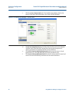
7. Click the
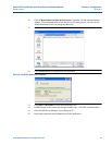
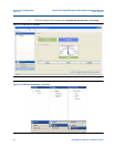
Frequency and Digital Output 1 tab. Follow the configuration instructions in the
AMS Device Manager - Guided Setup, Step 3b. Click
Apply, after you enter the data to
write the parameters to the meter.
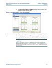
8. Click the
Frequency and Digital Output 2 tab. Follow the instructions in the AMS Device
Manager - Guided Setup, Step 3c to configure the Frequency and Digital Output 2
parameters. Click
Apply, after you enter the data to write the parameters to the meter.
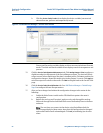
9. Click the
Temperature tab. Configure the input parameters including: Source (Live
Analog or Fixed), Min and Max input limits corresponding to 4 mA and 20 mA
respectively and the Low and High alarm limits. Click
Apply, after you enter the data to
write the parameters to the meter.
10. Click the
Pressure tab. Configure the input parameters including: Source (Live Analog or
Fixed), Min and Max input limits corresponding to 4 mA and 20 mA respectively and the
Low and High alarm limits. Select either
Gage or Absolute for the type of pressure
reading desired. If a live pressure transmitter is connected, select the type of reading
the transmitter outputs. If Absolute is selected, you must also enter the Atmospheric
pressure. Click
Apply, after you enter the data to write the parameters to the meter.
11. Click the
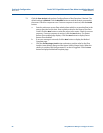
Digital Input tab. The default Digital Input 1 polarity is set to Normal for general
purpose or set to
Inverted when used for calibration. Click Apply, after you choose the
calibration data to write the parameters to the meter.
a. Calibration Polarity configuration parameter selections are:
– Digital Input 1 C
alibrate Active High
– Digital Input 1 C
alibrate Active Low


