


Daniel 3812 Liquid Ultrasonic Flow Meter Installation Manual Installation Manual List of Figures
3-9000-765 Rev D March 2013
List of Figures iii
List of Figures
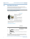
Figure 1-1 Daniel MeterLink download and registration ................................................................ 6
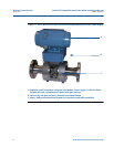
Figure 1-2 Direct mount electronics assembly with spl
it shroud .................................................... 7
Figure 1-3 Direct mount electronics with l
atched single band shrouds and remote display............ 8
Figure 1-4 Direct mount electronics with bolted single band shrouds and local display ................ 9
Figure 1-5 Direct mount electronics assembly with cl
amped band shrouds................................. 10
Figure 1-6 Remote mount electronics assembly with clamped band shrouds .............................. 11
Figure 1-7 Remote mount electronics assembly with split shrouds ............................................. 12
Figure 1-8 Optional local display and glass endcap ...................................................................... 13
Figure 1-9 Daniel 3810 Series Liquid Ultrasonic Meter ATEX
approval ......................................... 18
Figure 2-1 Direct mount meter electronics assembly with spli
t shroud........................................ 24
Figure 2-2 Remote mount meter electronics assembly with split shroud..................................... 25
Figure 2-3 Direct mount meter electroni
cs with bolted band shrouds ......................................... 26
Figure 2-4 Direct mount meter electroni
cs assembly with clamped band shrouds....................... 27
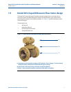
Figure 2-5 Piping recommendations unidirectional flow ............................................................. 29
Figure 2-6 Piping recommendations bidirectional flow................................................................ 30
Figure 2-7 Meter end flange with tapped flat-counterbore hole for hoist ring ............................ 33
Figure 2-8 Safety approved hoist ring and non-compliant eye
bolt .............................................. 34
Figure 2-9 90 Degree angle between slings ................................................................................. 35
Figure 2-10 Sling contacting electronics enclosure........................................................................ 36
Figure 2-11 Correct sling attachment............................................................................................ 41
Figure 2-12 Incorrect sling attachment.......................................................................................... 42
Figure 3-1 Transmitter Electronics Enclosure internal chassis ground .......................................... 46
Figure 3-2 External ground lug .................................................................................................... 47
Figure 3-3 CPU Module labeling and LED indicators..................................................................... 51
Figure 3-4 PC to meter serial connection wiring........................................................................... 55
Figure 3-5 CPU Module I/O connections...................................................................................... 55
Figure 3-6 CPU Module - Frequency/Digital outputs common ground ........................................ 59
Figure 3-7 CPU Module power source connections ..................................................................... 61
Figure 3-8 Transmitter electronics enclosure security latch ........................................................ 62
Figure 3-9 Direct or remote mount Tra
nsmitter Electronics Enclosure security seals ................... 63
Figure 3-10 Base Enclosure security seals ...................................................................................... 64
Figure 3-11 3812 Remote mount transmitter electronics opti
on................................................... 65
Figure 3-12 Bolted band shroud security seals - bottom view ........................................................ 66