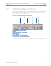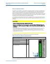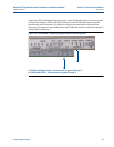
52 CPU Module labeling and LED indicators
Section 3: Electrical installation Daniel 3812 Liquid Ultrasonic Flow Meter Installation Manual
March 2013 3-9000-765 Rev D
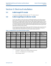
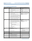
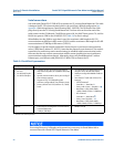
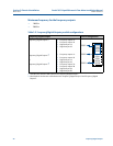
Table 3-2 CPU Module labeling and LED functions
CPU Module switch Function Switch position indicator or LED
WRITE PROT.
• Write-protect mode - with switch in the ON
position (default setting) protects configuration
and firmware overwrites.
• To write configuration changes or download
firmware to the meter change the switch to the
OFF position
Switch position
• ON - (default setting) enables write-
protection of the configuration and
firmware
• OFF - enables writing configuration
changes or downloading firmware
DHCP
• Dynamic Host Protocol Server - enables you to
communicate with a Daniel meter that is not
connected to a network.
• When the CPU Module switch is in the ON
position, the meter is enabled to act as a DHCP
server for a single DHCP client connected to the
Ethernet port using a crossover cable. This should
be used for peer to peer connections only.
• When the connection is made, select to use the
Meter Name in the meter instead of the Meter
Directory Name in order to keep all log files and
configurations separate from each meter.
Switch position
• ON - the meter is enabled to act as a
DHCP server for a single DHCP client
• OFF - disables the DHCP server
PORT A
• PORT A override - RS-232 serves as an override
during meter commissioning to establish com-
munications and in the event the user cannot
communicate with the meter due to an inadver-
tent communication configuration change. The
o
verride period is for two minutes
• Supports:
- auto-detected ASCII (Start bit 1, Data Bit 7,
Parity Odd/Even, Stop Bit 1)
- RTU (Start Bit 1, Data Bit 8, Parity none, Stop
Bit 1).
- Modbus protocols
• RS-232 Baud rate=19,200
• Modbus ID=32
Switch position
• ON - enables RS-232 PORT A override
• OFF - (default setting) disables
RS-232 PORT A
MEAS System color indicates metrology mode
• Acquisition mode
• Measurement mode
LED status
• Red flashing LED
• Solid red the Acquisition Module not
communicating with the CPU Module
• Green flashing LED
PWR
• 3.3V Power Indicator • Solid Green
LED 4
• Not used
LED 5
• Not used
RX
• RX signal (Port A for RS485 or RS232
communication) receiving data
• Flashing green (when receiving data)
TX
• TX signal (Port A for RS485 or RS232
communication) transmitting data
• Flashing green (when transmitting
data)
LINK
• ETH1Link user Ethernet connection • Solid green


