74 Field Setup Wizard
Section 4: Configuration Daniel 3812 Liquid Ultrasonic Flow Meter Installation Manual
March 2013 3-9000-765 Rev D
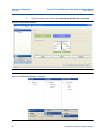
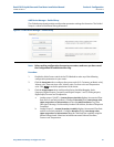
4.2 Field Setup Wizard
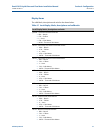
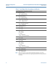
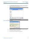
1. Use the Field Setup Wizard-Startup Page
and select the checkboxes that allow proper
configuration for your meter (Temperature, Pressure, Meter Corrections, and Meter
Outputs). Selections on this page will affect other configuration selections. Select
Next
to continue to General setup.
2. On General setup page configure the meter’s system units (U.S Customary or Metric
u
nits) volume units, flow rate time, low flow cutoff, contract hour and enable reverse
flow. Click
Next to continue to Frequency Outputs.
3. Configure Frequency output 1 and Frequency output 2 content (Daniel Liquid
U
ltrasonic Meters content is Uncorrected flow rate), flow direction, Channel B phase,
maximum frequency output (Hertz) and Full scale volumetric flow rate. Click
Next to
continue to Meter Digital Outputs.
4. Select the Meter Digital Output parameters for Digital output 1A, Digital output 1B,
Di
gital output 2A and Digital output 2B based on Frequency validity or flow direction.
if the output of the ultrasonic meter is reversed from what a flow computer is
e
xpecting, select Inverted Operation. This changes the digital output from a HIGH for a
TRUE condition to output a LOW for a TRUE condition. Click
Next to continue to Current
Outputs.
5. Current Outputs are based on Uncorrected (Actual) flow rate) content, flow direction
(F
orward, Reverse or Absolute) and Full scale volumetric flow rate used with output
(20mA maximum). Alarm action parameters determines the state the output will drive
during an alarm condition (High 20mA, Low - 4 mA, Hold last value, Very low - 3.5,
Very high 20.5 mA or None). Click
Next to continue to configure the HART® Output(s)
parameters.
6. HART® Output parameters include four Dyn
amic process variables (Primary,
Secondary, Third and Fourth variable. The Primary variable is set to match the Content
set for Current output 1. If a second current output is available, the Secondary variable
is set to match the Content set for Current output 1) Identification and HART® units
(volume units, Flow rate time units, Velocity units, Pressure and Temperature units).
Click
Next to continue to Temperature and Pressure.
7. Set the temperature and pressure scaling for analog inputs, enter fixed values, and set
al
arm limits for both.
8. Select
Finish to write the configuration settings to the meter.
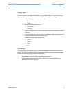
9. Configure the parameters for the local display. Use the drop-down arrow in the Display
It
ems list box and select or modify the Display items, the Display units and the Scroll
delay.


