


14 ImagePRO – Multi Format Image Processor Manual # 26-0302000-00 / Revision E
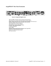
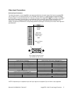
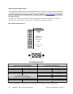
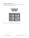
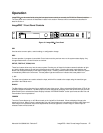
DVI-I Video In and Loop-Through Connectors (Universal Input 1-ImagePro-HD™)
Two DVI-I female connectors are located on the rear panel of the ImagePRO-HD™. One is used for Video input and
the other one is used for the buffered DVI-I Loop-Through. This Connector can be used with Analog inputs using the
DVI-I to HD-15 adaptor provided with ImagePRO-HD™.
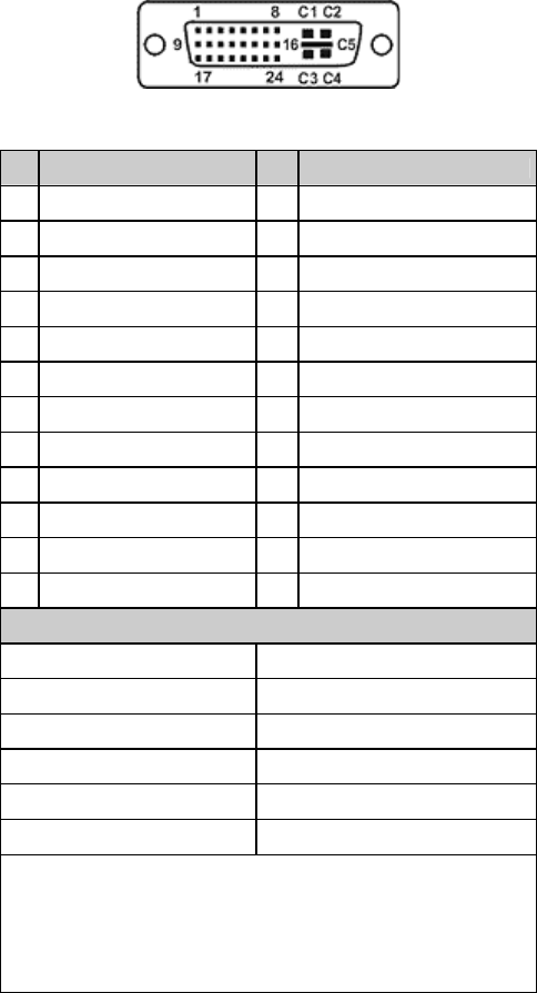
Pin Function Pin Function
1 T.M.D.S. Data2- 13
T.M.D.S. Data3+
2 T.M.D.S. Data2+ 14
+5V Power
3 T.M.D.S. Data2/4 Shield 15
ground (for +5V)
4 T.M.D.S. Data4- 16
Hot Plug Detect
5 T.M.D.S. Data4+ 17
T.M.D.S. Data0-
6 DDC Clock 18
T.M.D.S. Data0+
7 DDC Data 19
T.M.D.S. Data0/5 Shield
8 Analog Vertical Sync 20
T.M.D.S. Data5-
9 T.M.D.S. Data1- 21
T.M.D.S. Data5+
10 T.M.D.S. Data1+ 22
T.M.D.S. Clock Shield
11 T.M.D.S Data1/3 Shield
23 T.M.D.S. Clock+
12 T.M.D.S. Data3- 24
T.M.D.S. Clock-
MicroCross Pins
Pin Function
C1 Analog Red Video
C2 Analog Green Video
C3 Analog Blue Video
C4 Analog Horizontal Sync
C5 Analog Common Ground Return
Legend
DDC = Display Data Channel
T.M.D.S. = Transition Minimized Differential Signal