11
12
CHARGING SYSTEMS
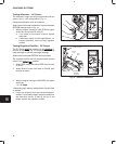
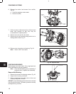
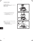
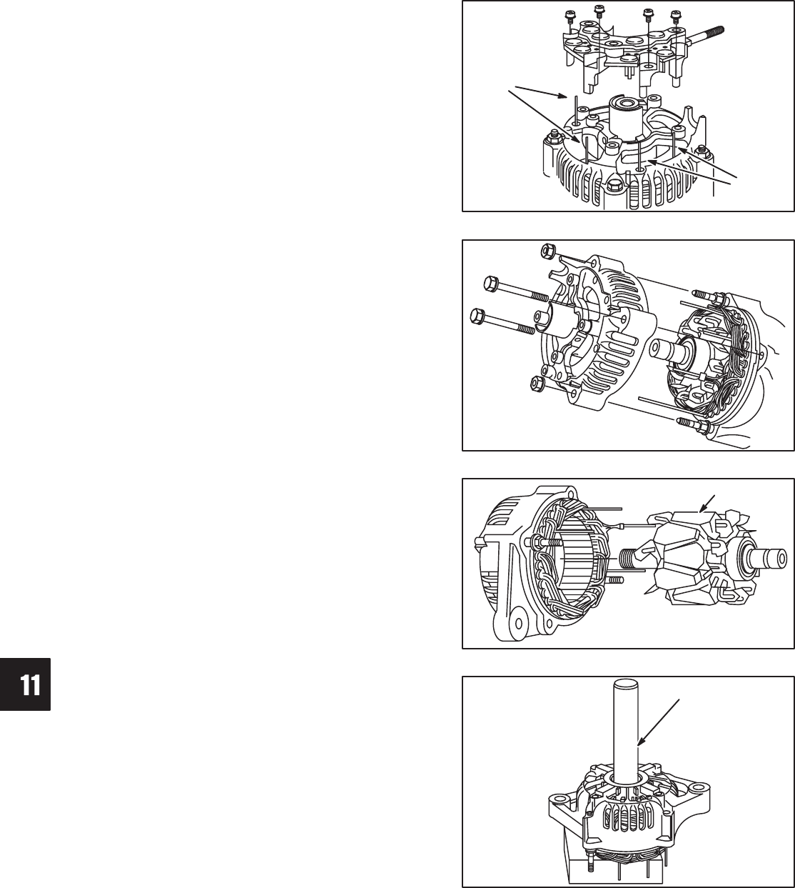
6. Remove four stator lead screws from rectifier,
Fig. 26.
a. Carefully straighten stator leads.
b. Remove rectifier.
Fig. 26 – Remove Rectifier
STATOR
LEADS
STATOR
LEADS
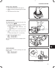
7. Scribe or place a reference mark on drive end and
brush end housing so that they may be
re-assembled in original position.
8. Remove two nuts and two thru bolts.
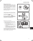
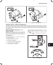
9. Remove brush end housing being careful not to
damage stator leads, Fig. 27.
Fig. 27 – Remove Brush End Housing
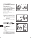
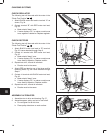
10. Remove rotor from drive end housing, Fig. 28.
Note: Stator is NOT removable.
Fig. 28 – Remove Rotor
ROTOR
CHECKING BEARINGS
Ball bearings must rotate freely. If any rough spots are
felt the ball bearing must be replaced.
Note: Rotor and ball bearing are an assembly. If
bearing is worn, replace rotor assembly.
Remove Ball Bearing
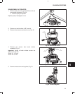
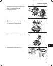
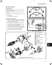
1. Remove four screws and bearing retainer, Fig. 29.
2. Support drive housing on blocks.
3. Press out bearing from pulley side of drive end
housing using driver #19416.
DO NOT re-use ball bearings that have been removed
from drive end housing. The bearing races are usually
damaged during removal.
Fig. 29 – Remove Bearing Retainer
19416 DRIVER


