


12
7
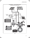
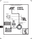
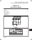
LUBRICATION SYSTEM
ASSEMBLE GEAR CASE
Install Oil Pump
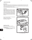
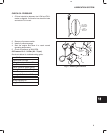
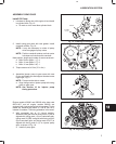
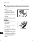
1. Lubricate oil pump rotor with engine oil and install
in cylinder block, Fig. 15.
a. ID mark on rotor must face cylinder block.
Fig. 15 – Installing Oil Pump Rotor
OIL PUMP
ROTOR
ID MARK
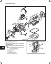
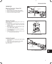
2. Install timing gear case with new gasket. Install
camshaft retainer, Fig. 16.
NOTE: It may be necessary to rotate oil pump
drive to engage oil pump rotors.
NOTE: Position camshaft retainer so that center
hole does not interfere with camshaft.
Note position, length and number of screws as shown.
a. M6 x 28 mm (M6 x 1.1”): 4
b. M6 x 18 mm (M6 x 0.7”): 3
c. M6 x 16 mm (M6 x 0.6”): 1
3. Torque screws to 8.0 Nm (70 in. lbs.).
Fig. 16 – Installing Timing Gear Case
B
A
C
A
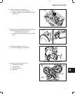
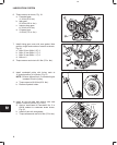
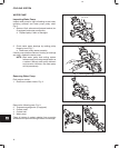
4. Assemble injector pump to gear case with new
O-ring and install nuts and support bracket screw
finger tight, Fig. 17.
NOTE: Pump must be able to rotate.
a. Align timing mark on injector pump with timing
mark on gear case.
NOTE: See Section 10 for injector pump
timing procedure.
Fig. 17 – Install Injector Pump
TIMING
MARKS
Engine models 432000 and 582000 after date code
990111007, and all engine models 522000 are
equipped with right angle helical timing gears. Timing
marks are identified by letters (A, AA, B, BB, etc.),
instead of numbers. The timing procedure is the same.
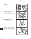
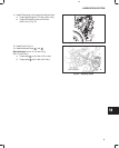
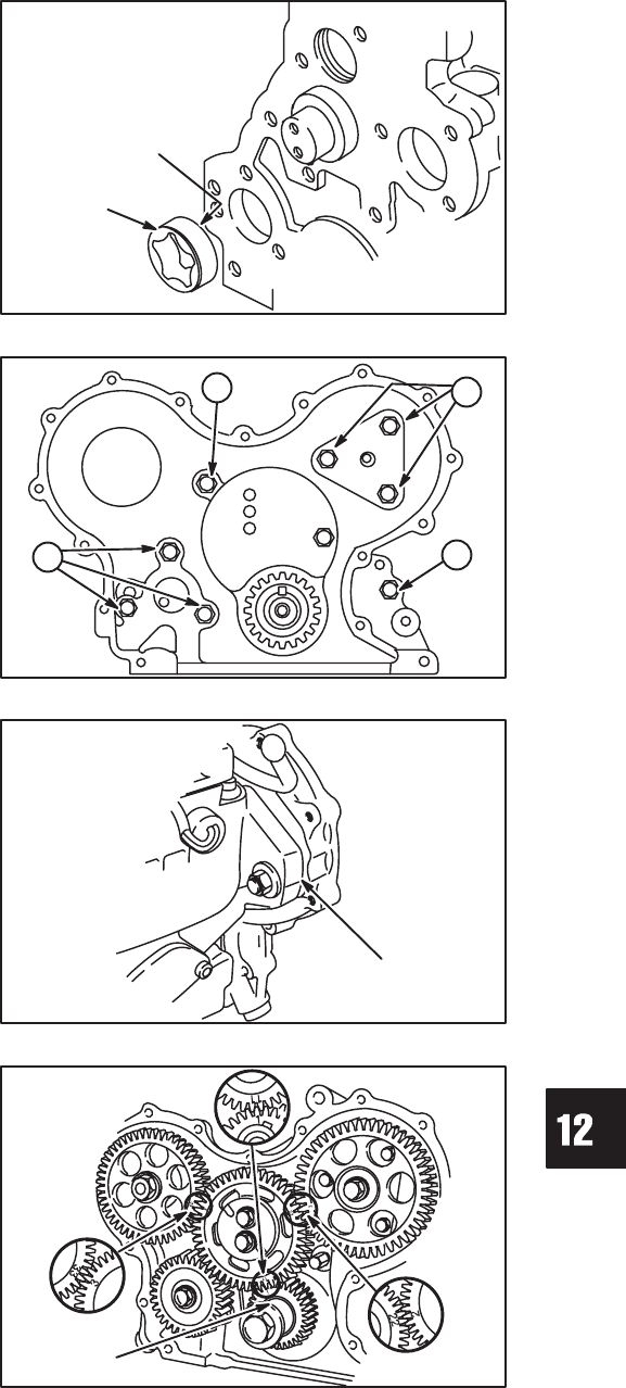
5. With crankshaft key at 12 o’clock position,
assemble idler gear so that timing mark 11 (AA) is
aligned with timing mark 1 (A) on crankshaft gear,
timing mark 22 (BB) is aligned with timing mark 2
(B) on camshaft gear, and timing mark 33 (CC) is
aligned with timing mark 3 (C) on injector pump
gear, as shown in Fig. 18.
a. Install oil pump gear.
Fig. 18 – Aligning Timing Marks
CRANK-
SHAFT
KEY
12 O’CLOCK