


2
3
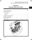
CYLINDER HEAD AND VALVES
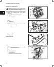
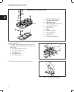
Fig. 5:
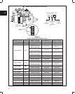
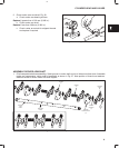
k. Fuel injector nozzles
l. Glow plugs
Fig. 5 – Remove Glow Plugs And Injectors
K
L
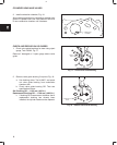
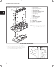
2. Set No. 1 piston at TDC, Fig. 6:
a. Rotate crankshaft pulley until timing mark on
pulley is aligned with reference point on timing
cover.
b. If intake and exhaust valves have clearance,
No. 1 piston is at TDC – compression stroke.
c. If intake and exhaust valves do not have
clearance, turn crankshaft pulley one
complete revolution. Valves will then have
clearance.
Fig. 6 – Set Cylinder No. 1 At TDC
REFERENCE
POINT
TIMING
MARK
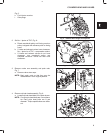
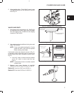
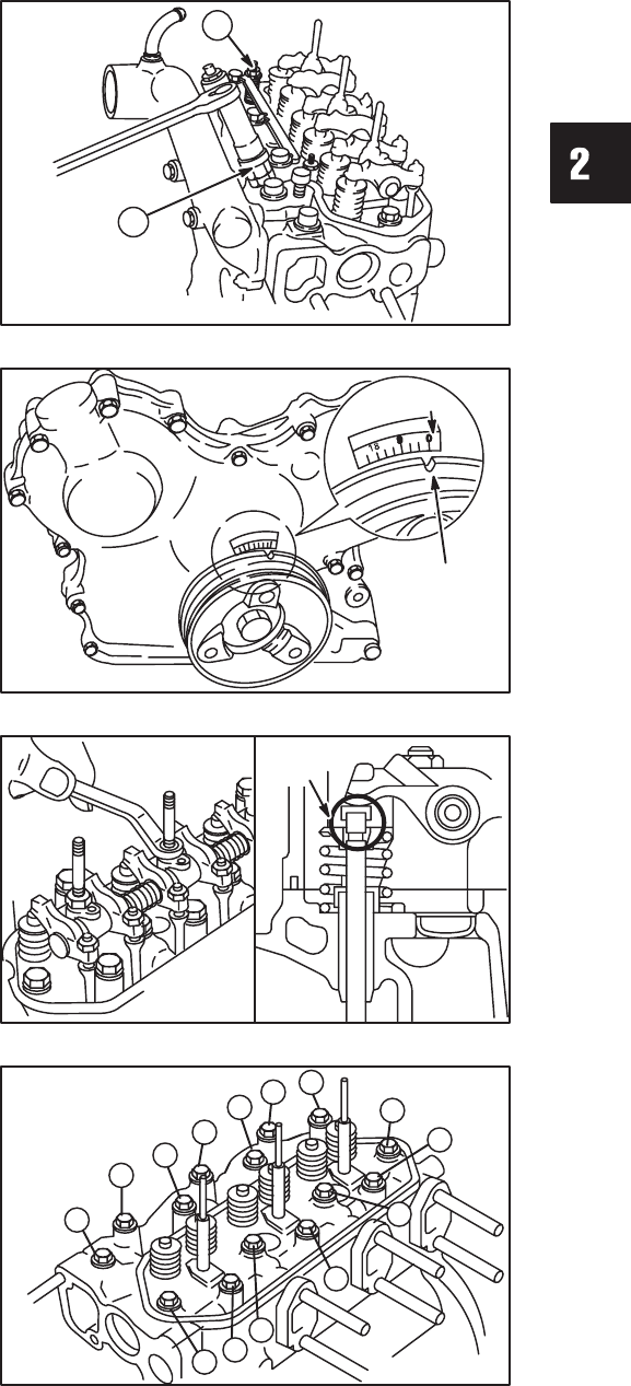
3. Remove rocker arm assembly and push rods,
Fig. 7.
a. Remove valve stem caps.
NOTE: Mark push rods so that they may be
reassembled in their original position.
VALVE
STEM
CAP
Fig. 7 – Remove Rocker Arm Assembly And Push Rods
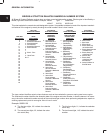
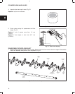
4. Remove cylinder head assembly, Fig. 8.
a. Loosen cylinder head bolts in the order shown.
NOTE: Current style head bolts are 9 mm diame-
ter. Early style head bolts are 8 mm
diameter. Torque specifications are differ-
ent.
Fig. 8 – Loosen Cylinder Head Bolts
3
4
5
6
7
1
2
8
12
11
10
9
14
13