


9
3
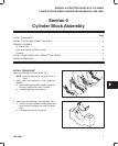
CYLINDER BLOCK ASSEMBLY
Rotate crankshaft so that crankpin is at bottom of
stroke. Then, lubricate cylinder walls, piston and rings,
bearings and crankpins.
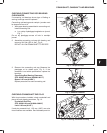
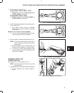
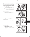
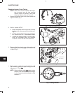
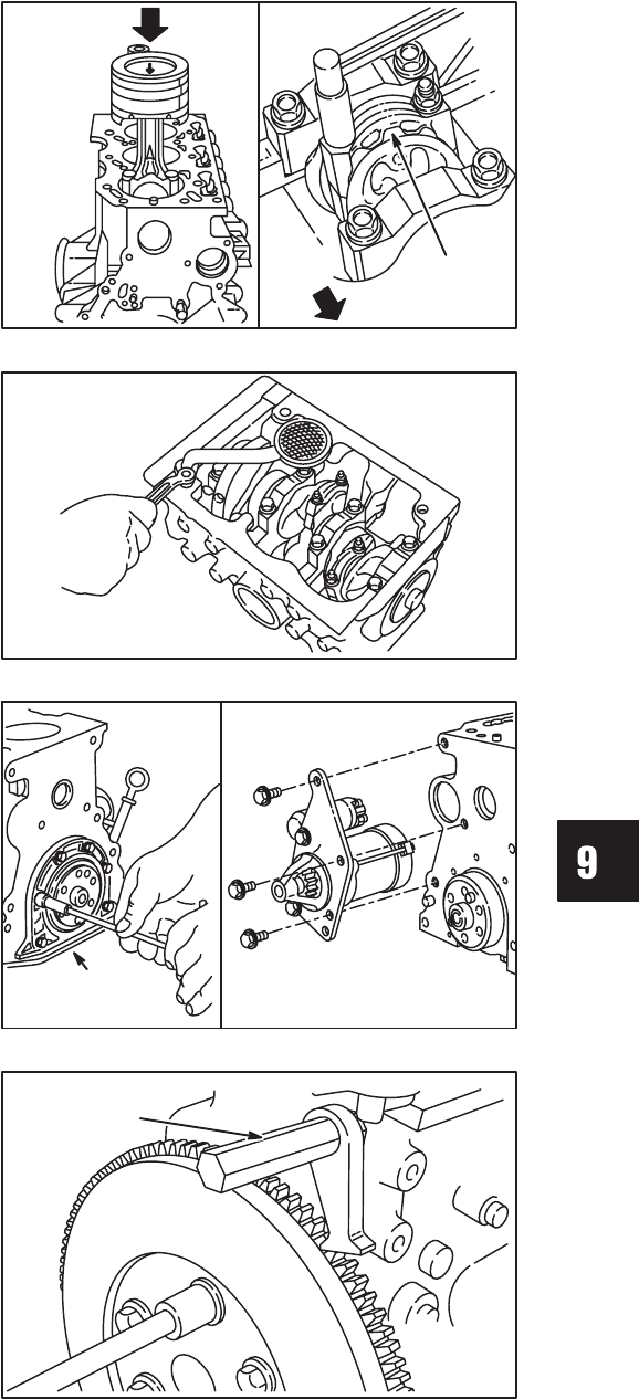
2. Using ring compressor, Tool #19070, install piston
and connecting rod assemblies with arrow on
piston facing front, Fig. 6.
a. Install connecting rod cap with ID mark facing
front. Lubricate threads and torque nuts to
34.0 Nm (320 in. lbs.).
NOTE: After torquing rod cap, make sure crank-
shaft rotates freely before proceeding to
next cylinder.
Fig. 6 – Installing Piston And Connecting Rod
ID MARK
FRONT
GENERAL ASSEMBLY
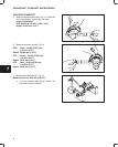
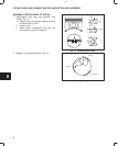
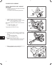
1. Install gasket, oil pick-up tube and strainer, Fig. 7.
a. Torque screws to 8.0 Nm (70 in. lbs.).
Fig. 7 – Installing Oil Pick-Up
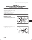
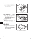
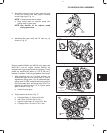
2. Install gasket and rear seal retainer, Fig. 8.
a. Torque screws to 6.0 Nm (50 in. lbs.).
3. Install starter motor.
a. Torque screws to 34.0 Nm (25 ft. lbs.).
Fig. 8 – Installing Rear Seal Retainer
REAR
SEAL
RETAINER
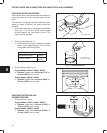
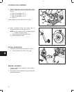
4. Install flywheel, Fig. 9.
a. Install flywheel holder, Tool #19418.
b. Apply Permatex No. 2 or similar sealant to
flywheel screws and torque to 47.0 Nm
(35 ft. lbs.).
Fig. 9 – Installing Flywheel
FLYWHEEL
HOLDER