


11
25
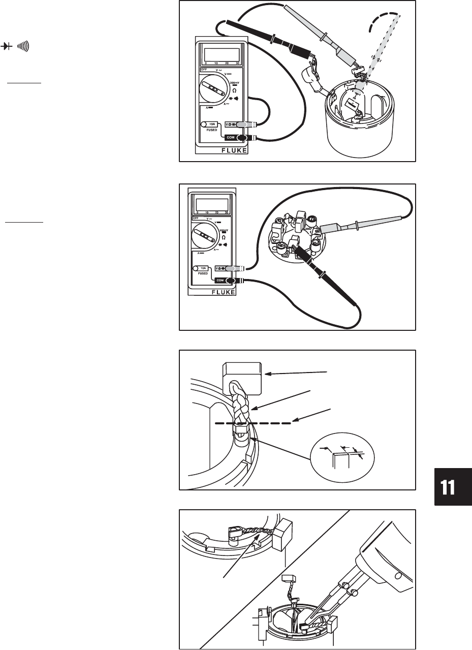
STARTER SYSTEM
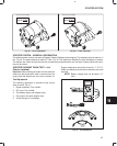
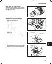
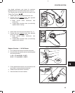
Use digital multimeter and check for continuity
between field coil wire and brushes shown, Fig. 70.
The following test will be made with the meter in the
“Diode Test Position” .
1. Attach either meter test lead to field coil wire.
2. Contact first one positive brush, then opposite
brush with other test lead as shown.
a. Meter should make continuous tone
(continuity).
b. If meter does not make a tone, (no continuity)
replace starter housing.
Fig. 70 – Checking Brushes
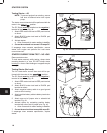
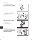
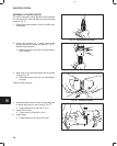
3. Attach either test lead to brush retainer, Fig. 71.
4. Contact first one negative brush, then opposite
brush with other test lead as shown.
a. Meter should make continuous tone
(continuity).
b. If meter does not make a tone, (no continuity)
replace brush retainer.
Fig. 71 – Checking Brushes
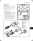
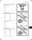
Replace Brushes – 1.0 KW Starter
1. Cut off brush lead wires at terminals as shown.
2. Use a fine file and carefully remove remaining lead
wire from terminals.
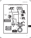
L: 2.3 – 2.7 mm (0.090 – 0.106”)
W: 6.5 – 7.5 mm (0.255 – 0.295”)
Fig. 72 – Clean Terminals
L
W
BRUSH
LEAD WIRE
CUT
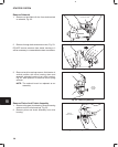
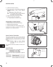
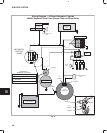
3. Crimp replacement brushes over terminals so that
wires face in counterclockwise direction.
4. Solder brush lead wires to terminals.
5. Insert brushes into brush retainer.
Fig. 73 – Install Brushes
COUNTERCLOCKWISE