


2
14
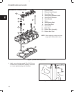
CYLINDER HEAD AND VALVES
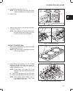
ADJUST VALVES
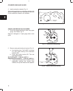
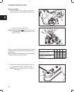
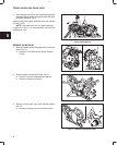
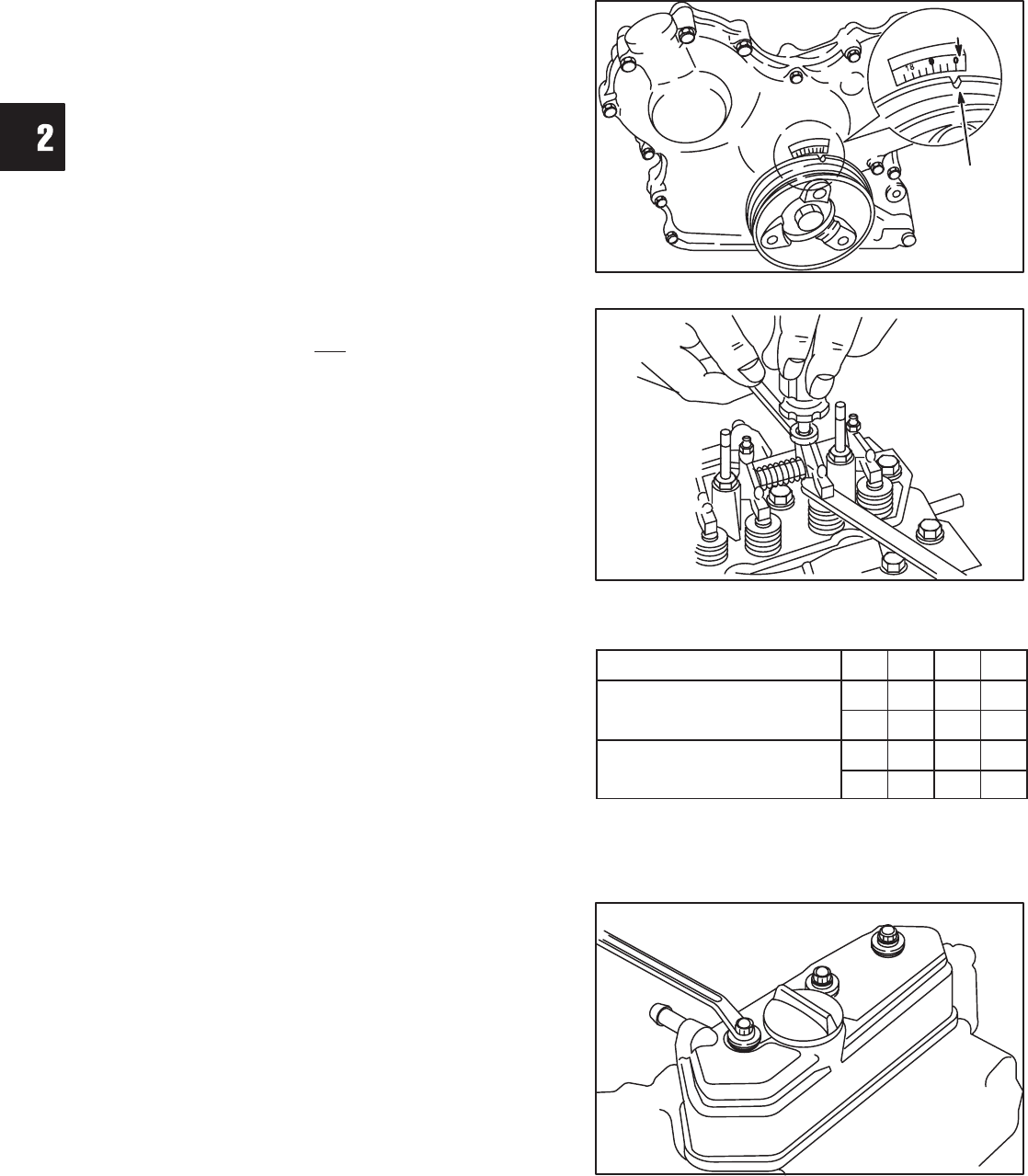
1. Before adjusting valves, make sure that No. 1
cylinder is at TDC – compression stroke, Fig. 42.
Fig. 42 – Set Cylinder No. 1 at TDC
REFERENCE
POINT
TIMING
MARK
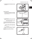
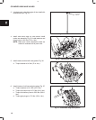
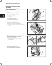
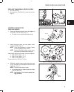
a. Adjust valves and check, Fig. 43.
Valve Clearance (cold) IN and EX 0.20 mm (0.008 in.)
b. Torque adjusting screws and jam nuts to 11.0
Nm (95 in. lbs.).
Fig. 43 – Adjust Valve Clearances
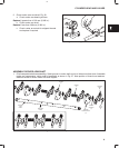
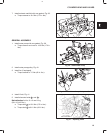
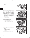
With No. 1 piston at TDC of compression stroke, check
and adjust valve clearances for cylinders shown in
chart at right.
Rotate crankshaft one complete turn (360°)"clockwise
to check and adjust remaining valves.
Piston Position Cylinder 1 2 3
No. 1 piston at TDC, of
IN
l l
No
.
1 piston at TDC
,
of
compression stroke
EX
l l
Rotate Crankshaft 360°
IN
l
Rotate Crankshaft 360
clockwise
EX
l
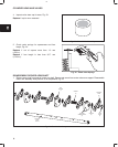
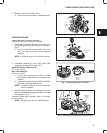
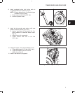
2. Install valve cover with new rubber seal, Fig. 44.
a. Torque cover nuts to 7.0 Nm (50 in. lbs.).
NOTE: Make sure rubber seal is in groove in
valve cover.
Fig. 44 – Install Valve Cover