


11
24
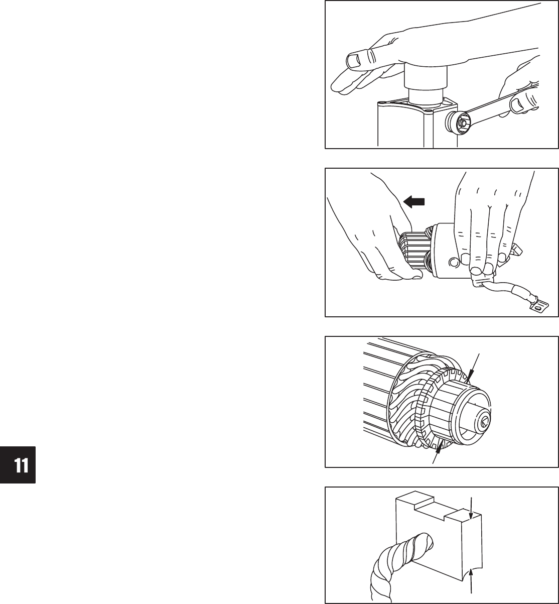
STARTER SYSTEM
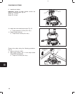
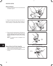
9. Install new plunger and spring.
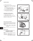
10. Place bearing driver, Tool #19422 on plunger and
compress plunger to end of travel. Maintain
pressure.
a. Torque nuts to 17 Nm (150 in. lbs.).
Note: This provides proper contact alignment
with plunger and contact plates.
11. Clean contact plates and plunger contacts.
12. Install cover plate with new gasket.
a. Torque screws to 4 Nm (35 in. lbs.).
Fig. 66 – Aligning Contact Plates
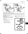
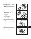
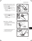
DISASSEMBLE STARTER MOTOR
1. Remove starter motor from drive housing.
2. Remove screws and end cap.
3. Remove armature from motor housing, Fig. 67.
If armature drive splines or armature bearings are
damaged or worn, replace armature.
Fig. 67 – Disassemble Starter Motor
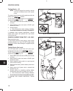
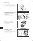
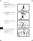
Inspect Armature Commutator
The armature commutator may be cleaned with fine
sandpaper. DO NOT use emery cloth. Commutator
may be machined to no less than 29.0 mm (1.142”),
Fig. 68.
NOTE: Minimum depth of slots between
commutator bars after machining is 0.2
mm (.008”).
The armature should be checked for shorts with a
growler.
Fig. 68 – Commutator Specifications
29.0 mm
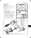
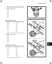
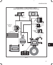
Inspect Brushes
Minimum brush dimension is shown below Fig. 69.
1.0 KW Starter: 9 mm (.350”).
1.2 KW Starter: 10 mm (.400”).
If brushes are worn less than specification, replace as
follows.
1.0 KW Starter: Replace brush retainer and brushes
on starter housing.
1.2 KW Starter: Starter housing and brush retainer
must be replaced as an assembly.
Fig. 69 – Minimum Brush Dimension
1.2 KW: 10 mm
1.0 KW: 9 mm