


2
7
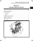
CYLINDER HEAD AND VALVES
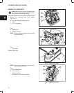
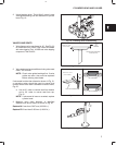
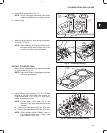
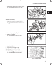
3. Using bushing driver, Tool #19416, press in new
valve guide bushing until tool bottoms on cylinder
head, Fig. 19.
Fig. 19 – Installing Valve Guide Bushing
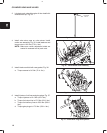
VALVES AND SEATS
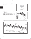
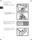
1. Valve faces may be resurfaced to 45°. See Fig. 20
for dimensions for valves. Lap valves and seats
with valve lapping Tool, #19258 and valve lapping
compound, Tool #94150.
Fig. 20 – Valve Dimensions
SEATING AREA CENTERED
ON VALVE FACE
(1/16” TO 3/64”)
(.040”)
MINIMUM
0.8 mm TO 1.2 mm
1.0 mm
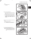
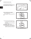
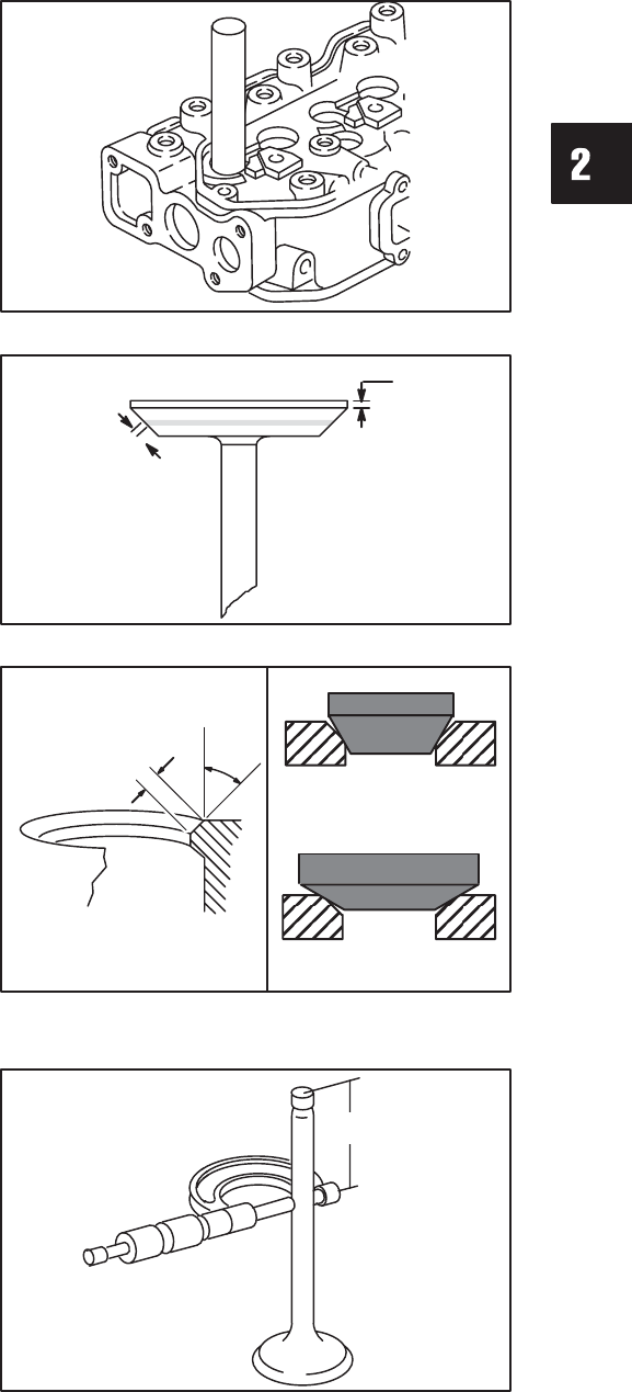
2. Valve seats may be reconditioned using valve seat
cutter, Tool #19446.
NOTE: Check valve guide bushings first. If valve
guides are worn, they must be replaced
before refacing valve seats
If valve seat is wider than dimension shown in Fig. 21,
a narrowing cutter should be used to ensure that
contact area of valve seat is centered on face of valve,
Fig. 20.
a. Use a 60° cutter to narrow seat from bottom
and a 30° cutter to narrow seat from top,
Fig. 21.
NOTE: If valve seat is loose or cracked, replace
cylinder head.
Fig. 21 – Valve Seat Dimensions
45°
VALVE SEAT DIMENSIONS
60° CUTTER
30° CUTTER
(1/16” TO 3/64”)
0.8 mm TO 1.2 mm
3. Measure valve stem diameter at specified
distance from end of valve, as shown in Fig. 22.
Replace IN if less than 5.927 mm (0.2333 in.).
Replace EX if less than 5.923 mm (0.2332 in.).
Fig. 22 – Measure Valve Stem Diameter
35 mm
(1.38”)