


10
9
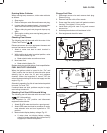
FUEL FILTER
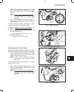
Draining Water Collector
When warning lamp comes on, drain water collector
as follows:
1. Stop engine.
2. Place a drain pan under filter and loosen vent plug.
3. Loosen drain plug approximately 1 turn and drain
water from filter until only fuel flows from filter.
4. Tighten drain plug and vent plug and wipe up any
spills.
5. Start engine, making sure warning lamp goes out.
Check for leaks.
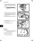
Change Fuel Filter
1. Disconnect sensor wire and remove drain plug.
Discard O-ring.
2. Remove fuel filter with a filter wrench.
3. Screw new filter on by hand until gasket contacts
housing. Then tighten 1/3 turn more.
4. Install drain plug with new O-ring and connect
sensor wire.
5. Activate primer button until resistance is felt.
6. Start engine and check for leaks.
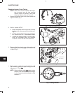
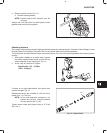
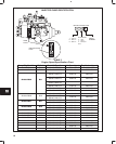
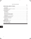
Checking Float Sensor
The following test will be made with the meter in the
‘‘Diode Test Position” .
Disconnect sensor wire from equipment harness and
remove float sensor from fuel filter.
1. Attach a meter test lead to each terminal in
connector.
2. While holding drain plug in vertical position, raise
float to end of travel, Fig. 20.
a. Meter should make a continuous tone.
3. Now lower float
a. Meter should display OL.
Replace drain plug and float sensor if not to specification.
Fig. 20 – Checking Sensor
FLOAT
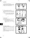
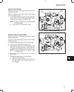
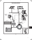
FUEL SHUT-OFF SOLENOID
When the ignition switch is turned to the ‘‘On” and
‘‘Start” position the fuel shut off solenoid valve opens
allowing fuel to enter the fill port and pressure
chamber. When the keyswitch is turned ‘‘Off” the
solenoid closes shutting off the the fuel supply and the
engine, Fig. 21.
Solenoid is operating if a click is heard when keyswitch
is turned ‘‘On” and ‘‘Off.”
If solenoid does not click, problem may be in equip-
ment wiring to solenoid.
Fig. 21 – Fuel Shut-Off Solenoid
FUEL
SHUT-OFF
SOLENOID
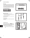
Checking Fuel Shut-Off Solenoid Wiring
The following test will be made with the meter in the
(DC Volts position).
Turn keyswitch to ‘‘Off” position and disconnect
equipment solenoid wire.
1. Attach BLACK meter test lead to a good ground.
2. Attach RED meter test lead to connector in equip-
ment solenoid wire and turn keyswitch to ‘‘On”
position.
3. Meter should display battery voltage, Fig. 22.
a. If meter does not display battery voltage,
check for broken solenoid wire, blown fuse (if
equipped) or defective keyswitch.
Fig. 22 – Testing Solenoid Wiring
EQUIPMENT
WIRING HARNESS
CONNECTOR