2
5
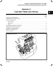
CYLINDER HEAD AND VALVES
INSPECT AND REPAIR
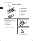
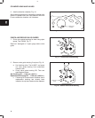
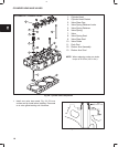
1. Check cylinder head mounting surfaces, Fig. 12
and Fig. 13.
Be sure all gasket material is removed from surfaces
before checking. Use a gasket scraper if necessary.
a. Inspect cylinder head for cracks or damage.
b. Use a straight edge and check cylinder head
lower surface for distortion.
Fig. 12 – Check Cylinder Head For Distortion
STRAIGHT
EDGE
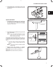
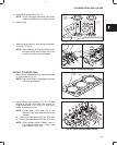
Fig. 13:
c. Check intake and exhaust manifold mounting
surfaces.
If mounting surfaces are distorted more than 0.1 mm
(0.004 in.), the cylinder head must be replaced.
It is not recommended that cylinder head
mounting surfaces be resurfaced.
NOTE: Intake manifold and exhaust manifold
may be checked in the same manner. Use
same specifications as cylinder head.
Fig. 13 – Check Cylinder Head For Distortion
CHECK COMBUSTION CHAMBER
Engine Model 522000: combustion chambers are
not replaceable.
Engine Models 432000 and 582000 with date code
after 990111007: combustion chambers are not
replaceable.
NOTE: Only Engine Models 432000 and 582000
with date code before 981225006 have
replaceable combustion chambers.
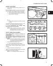
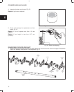
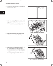
1. Check combustion chamber, Fig. 14.
a. Use a straight edge and feeler gauge.
If combustion chamber protrudes more than 0.05 mm
(.002 in.) above surface of cylinder head, it must be
replaced.
Fig. 14 – Check Combustion Chamber
COMBUSTION
CHAMBER
COMBUSTION
CHAMBER
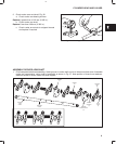
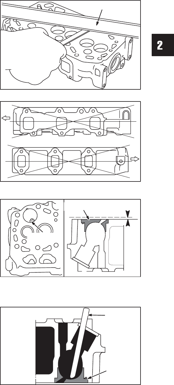
2. Remove combustion chamber, Fig. 15.
Insert a 10 mm brass rod through injector nozzle hole
and drive out combustion chamber.
NOTE: Do not damage threads in injector hole.
Fig. 15 – Remove Combustion Chamber
BRASS ROD
COMBUSTION
CHAMBER


