


11
8
CHARGING SYSTEMS
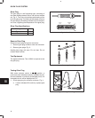
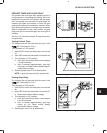
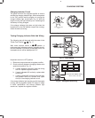
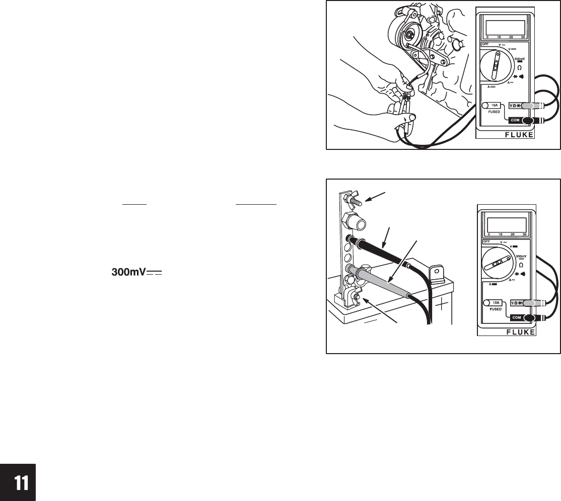
Testing Alternator – AC Output
The alternator output test will be performed with the
meter in the V~ (AC volts) position, Fig. 14.
Disconnect alternator wires at connector.
Attach meter test leads to alternator output connectors
BEFORE starting engine, Fig. 14.
1. With the engine running at 3300 RPM the output
should be no less than 28 volts AC.
a. If no output or low output is found, replace
alternator.
b. If alternator output is within specification, re-
connect alternator wires and test regulator
rectifier.
Fig. 14 – Testing Alternator Output
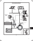
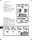
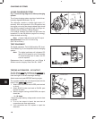
Testing Regulator-Rectifier – DC Output
The DC Shunt must be installed on the negative (-)
terminal of the battery, Fig. 15. All connections must be
clean and tight for correct amperage readings.
Attach meter test leads BEFORE starting engine.
The regulator-rectifier test will be performed with the
meter in the position.
1. Attach RED meter test lead to RED post terminal
on shunt.
2. Attach BLACK meter test lead to BLACK post
terminal on shunt.
Fig. 15 – DC Shunt Installation
BLACK
LEAD
RED
LEAD
NEGATIVE
BATTERY
TERMINAL
ATTACH NEGATIVE
BATTERY CABLE
3. With the engine running at 3300 RPM, the output
should be:
* 4 – 14 Amps
* Depending upon battery voltage and/or current draw
on system.
4. If no or low output is found, be sure that regulator-
rectifier is grounded properly and all connections
are clean and secure. If there is still no or low
output, replace the regulator-rectifier.