


10
5
INJECTOR PUMP
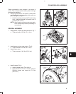
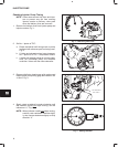
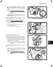
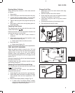
5. Slowly rotate crankshaft clockwise until timing
mark on pulley aligns with reference point on gear
case cover (TDC), Fig. 5. Note dial indicator
reading.
NOTE: Do not rotate crankshaft past TDC. If
crankshaft is rotated past TDC rotate
crankshaft back to ‘‘0” and repeat
procedure.
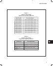
6. Refer to timing specification tables on page 3 for
correct specification by engine model and type or
code number.
If indicator reading is within specification, injector
pump is properly timed. Proceed to step 6.
If indicator reading is not within specification, see
procedure for adjusting injector pump timing.
Fig. 5 – Checking Timing
METRIC INDICATOR
SHOWN
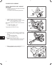
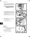
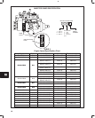
7. Remove timing gage and install distributor screw
with new washer, Fig. 6.
a. Torque screw to 17.0 Nm (150 in. lbs.).
8. Install fuel delivery lines.
a. Torque to 25.0 Nm (220 in. lbs.).
Fig. 6 – Install Distributor Screw
DISTRIBUTOR
SCREW
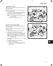
Adjusting Injector Pump Timing
Refer to timing specification tables on page 3 for correct
specification by engine model and type or code number.
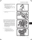
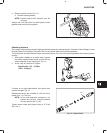
1. Loosen injector pump mounting nuts and pump
support bracket screw, Fig. 7. Rotate pump toward
cylinder head as far as it will go.
NOTE: Loosen nuts and screw only enough to
allow pump to be rotated with some
resistance.
Perform Steps 2 through 4 as described in ‘‘Checking
Injector Pump Timing”.
Fig. 7 – Loosen Pump
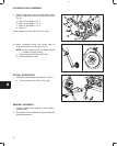
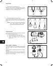
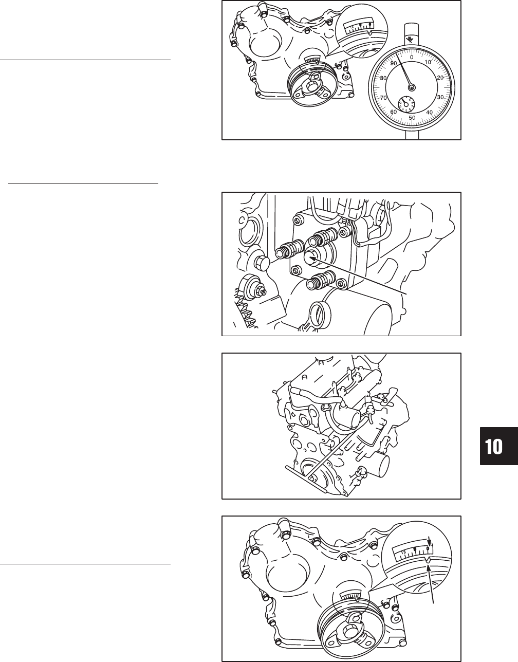
2. Slowly rotate crankshaft clockwise until timing
mark on pulley aligns with reference point on gear
case cover (TDC), Fig. 8.
NOTE: Do not rotate crankshaft past TDC. If
crankshaft is rotated past TDC rotate
crankshaft back to ‘‘0” and repeat
procedure.
Fig. 8 – Align Timing Marks
REFERENCE
POINT
TIMING
MARK