


8
3
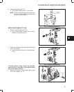
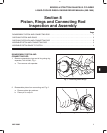
PISTON, RINGS AND CONNECTING ROD INSPECTION AND ASSEMBLY
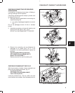
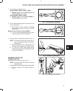
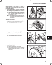
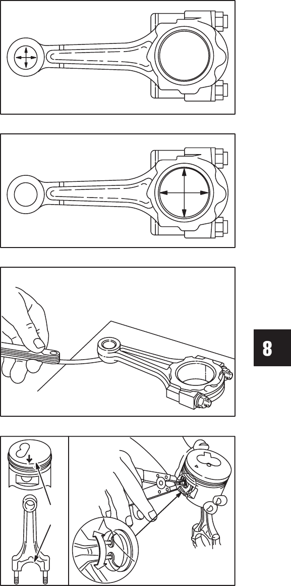
2. Check piston pin bearing, Fig. 7.
Engine Models: 432447, 522447, 582447
a. Replace if greater than 18.03 mm (0.710”) or
.01 mm (.0004”) out of round.
Engine Models: 58A447, 588447
b. Replace if greater than 21.03 mm (0.828”) or
.01 mm (.0004”) out of round.
Fig. 7 – Checking Piston Pin Bearing
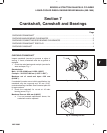
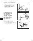
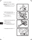
3. Check crankpin bearing end of connecting rod for
out of round, Fig. 8.
a. With bearing inserts removed, assemble
connecting rod cap and torque to 36.0 Nm
(320 in. lbs.).
Maximum out of round: 0.02 mm (0.0008”)
b. If out of round exceeds specification shown,
the connecting rod must be replaced.
Fig. 8 – Checking Crankpin Bearing End
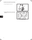
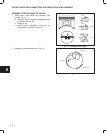
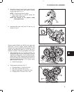
4. Check for bent or twisted connecting rod, Fig. 9.
NOTE: Thrust faces must be free of any burrs or
nicks or connecting rod will not lay flat on
surface plate.
a. With connecting rod on a surface plate, any
distortion will be evident by a rocking motion.
b. If a 0.05 mm (0.002”) feeler gauge can be
inserted at piston pin end of connecting rod the
rod must be replaced.
Fig. 9 –Checking Connecting Rod
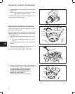
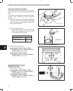
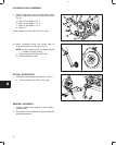
ASSEMBLE PISTON AND
CONNECTING ROD
Assemble piston to connecting rod, Fig. 10.
NOTE: Arrow on piston and ID mark on rod must
face same side.
1. Lubricate piston pin with engine oil before assembly.
a. Be sure retainers are seated properly in
piston.
Fig. 10 – Assembling Piston And Rod
ID
MARK