


Workman MDEPage 5 -- 12Chassis
C. Install brake hose clip onto cap screw. Secure
spindle to A--arm hub with cap screw and lock nut.
Torque fasteners from 75 to 100 ft--lb (102 to 135
N--m).
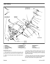
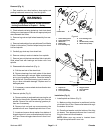
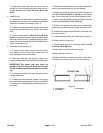
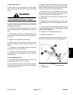
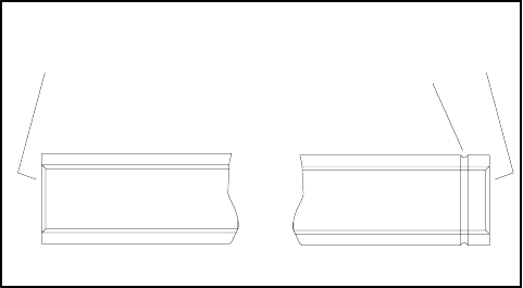
2. Install tie rod:
A. Position tie rod assembly to spindle and pitman
arm so that tie rod groove (LH threads) is orientated
toward the left s ide of the machine (Fig. 6).
B. Insert tie rod ball joints down through the spindle
and up through the Pitman arm. Secure with castle
nuts.
C. Torque castle nuts from 20 to 25 ft--lb (28 to 33
N--m) to secureball jointwhile aligningcastle nutslot
with holein ball joint stud.If necessaryto align holes,
castle nut torque may be slightly more than specifi-
cation. Install cotter pin.
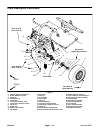
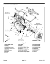
3. Assemble wheel hub (Fig. 4):
A. If bearing cups were removed from the wheel
hub, press inner and outer cups into the hub until
they seat against the hub shoulder.
B. Pack both bearings with grease. Install inner
bearingintothe cuponinboard sideofthewheel hub.
IMPORTANT: The wheel hub seal must be
pressed in so it is flush with the end of the hub.
The lip of the seal mustbe toward the inner bear-
ing.
C. Lubricate the inside of the new seal and press it
into the wheel hub.
D. If brake rotor was removed, position rotor to hub
with chamferededge towardhub. ApplyLoctite#242
(or equivalent)to sockethead screwsand secure ro-
tor to hub.
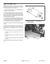
4. Slide wheel hub assembly onto spindle. Install outer
bearing, tab washer and jam nut onto spindle.
5. Rotate the wheel by hand and tighten the jam nut
from 75 to 100 in-lb (8.5 to 11.3 N--m) to set the bear-
ings. Then, loosen the nut until the hub has end play.
6. Again, rotate the wheel by hand and tighten the jam
nut from 15 to 20 in-lb (1.7 to 2.3 N--m).
7. Position nut retainer over jam nut and install cotter
pin through spindle shaft hole. Install dust cap to hub.
8. Install brake caliperto spindle (see Front Brake Cali-
per in this section).
9. Install wheel assembly with valve stem facing out.
10.Lower machine to ground.
11.Torque wheel lug nuts in a crossing pattern from 45
to 65 ft--lb (62 to 88 N--m).
12.Lubricate tie rod ball joints and king pin.
13.Align steering and toe--in.
14.Make sure that front wheels move fully in both direc-
tions without contacting any front end components.
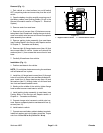
1. Tie rod groove
2. LH threads
3. RH threads
Figure 6
1
2
3
TIE ROD TUBE