


Rev. A
Workman MDE
Page 3 -- 12
Electrical System
Accelerator Potentiometer Adjustment (Potentiometer with Short Lever)
NOTE: The following adjustment procedure should be
usedon vehiclesthathavea potentiometerthatincludes
a s hort lever (Figure 14). If potentiometer has a long le-
ver, use the procedure on the following page.
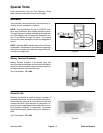
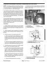
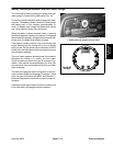
The accelerator potentiometer is used as one of the in-
puts for the vehicle controllerand is attachedto the ped-
al frameunder the dash(Fig. 13). Acollar with roll pinon
the acceleratorpedal shaft positionsthe acceleratorpo-
tentiometer lever. Potentiometers with a short lever use
a roll pin that extends approximately 1 1/2 inches (38
mm) out of the collar.
If theaccelerator potentiometer is outof adjustment, the
diagnostic light on the dash will flash six (6) times. Addi-
tionally, if vehicle movement is erratic and jerky, poten-
tiometer adjustment and calibration of the accelerator
system should be performed.
Adjustment
1. Position vehicle on a level surface, turn on/off switch
OFF andremove key. Makesure thataccelerator poten-
tiometer is securely attached to the pedal frame of the
machine.
2. Check accelerator switch adjustment and adjust if
necessary (see Accelerator Switch Adjustment in this
section).
3. Check movement of the potentiometer lever:
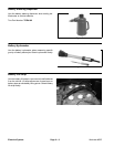
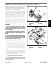
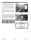
A. With the accelerator pedal released, the roll pin
on the throttle position collar should keep the poten-
tiometer lever from 0.050” to 0.100” (1.3 to 2.5 mm)
from the lower stop on the potentiometer body (Fig-
ure 14).
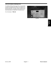
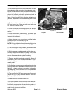
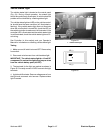
B. Withtheaccelerator pedalfullydepressed, thein-
put lever of the potentiometer should not contact the
upper stop on the potentiometer body (Figure 15).
4. If potentiometer lever movement is incorrect, adjust
location of collar on accelerator pedal shaft:
A. Loosen two (2) set screws that secure throttle
position collar to throttle pedal shaft and reposition
collar to allow correct potentiometer movement.
Make sure that there is clearance between roll pin
and side of potentiometer lever to prevent binding.
B. Remove set screws one at a time from collar and
apply Loctite #242 (or equivalent) to set screw
threads. Install and tighten set screws to secure col-
lar to accelerator pedal shaft.
C. Recheck potentiometer lever movement.
5. Calibrate accelerator system after any accelerator
potentiometeradjustment (seeAcceleratorSystem Cal-
ibration in this section).
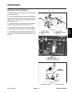
1. Potentiometer
2. Accelerator pedal
3. Throttle position collar
4. Roll pin
5. Set screw (2 used)
Figure 13
1
2
3
4
5
1. Potentiometer lever (accelerator pedal released)
2. Potentiometer lower stop
3. Gap of 0.050” to 0.100” (1.3 to 2.5 mm)
Figure 14
1
2
3
1. Potentiometer lever (accelerator pedal fully depressed)
2. Potentiometer upper stop
3. No lever contact with stop
Figure 15
1
2
3