


Workman MDE
Page 3 -- 41
Electrical System
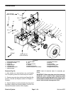
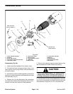
Assembly (Fig. 56)
NOTE: After the motor has been disassembled, it is
recommended that a new commutator end head bear-
ing be installedbecause theremoved bearingmay have
been damaged during disassembly. Although the bear-
ing may appear andfeel good,the bearing couldb e ”bri-
nelled” (races or balls deformed) and may exhibit noise
and vibrationproblems or failwithin arelatively shortpe-
riod of service. When installing new bearing, always
press against the race that is absorbing the pressure or
bearing damage may occur.
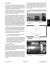
1. After servicing the commutator and brushes, re--as-
semble the wiring in the commutator end head as origi-
nally found. Ensure the wiring does not contact metal
androtating parts.Also,make surethatthe wiringallows
the brushes to move unrestricted in the brush holders.
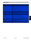
2. Press a new bearing into the commutator end head,
pressingon thebearingouterrace only(Fig. 61).Secure
bearing with retaining ring.
3. Position the commutator end head to the frame and
field assembly and secure with four (4) bolts. Torque
bolts from 120 to 140 in--lb (13.6 to 15.8 N--m).
4. Ensure the brushes are pushed out of the way.
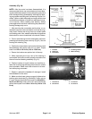
5. While supporting the inner--race of the bearing in
commutator end head,carefully press the armatureinto
the end head and bearing assembly (Fig. 61).
6. Position brushes in brush holders and carefully re-
lease the brush springs allowing the brushes to contact
the commutator. Make sure brush shunts do not inter-
fere with spring movement.
7. Repair or replace the headband if damaged. Install
the headband on the motor.
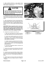
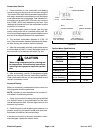
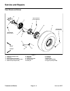
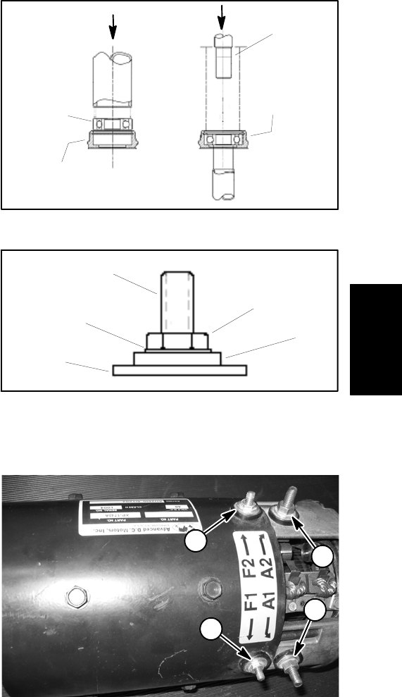
8. Make sure that lower nuts are properly tightened on
traction motor terminals (Fig. 62 and 63). Lower nuts on
F1 andF2 terminalsshould be torqued from50 to60 in--
lb (5.7 to 6.8 N--m). Lower nuts on A1 and A2 terminals
should be torqued from 110 to 140 in--lb (12.4 to 15.8
N--m).
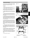
Figure 61
ARMATURE
ASSEMBLY
RETAINING RING
PRESS FIXTURE
MUST HOLD
INNER RACE
STATIONARY
PRESS FIXTURE
MUST PRESS
AGAINST
OUTER RACE
BEARING
END HEAD
MUST BE HELD
STATIONARY
INSTALLED
IN END HEAD
BEARING AND
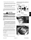
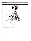
1. Terminal
2. Lower nut
3. Flat washer
4. Insulating washer
5. Motor housing
Figure 62
3
4
5
2
1
1. A2 terminal
2. F2 terminal
3. F1 terminal
4. A1 terminal
Figure 63
1
2
3
4
Electrical
System