


Workman MDE
Page 3 -- 35
Electrical System
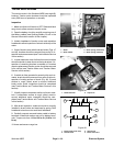
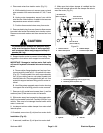
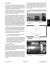
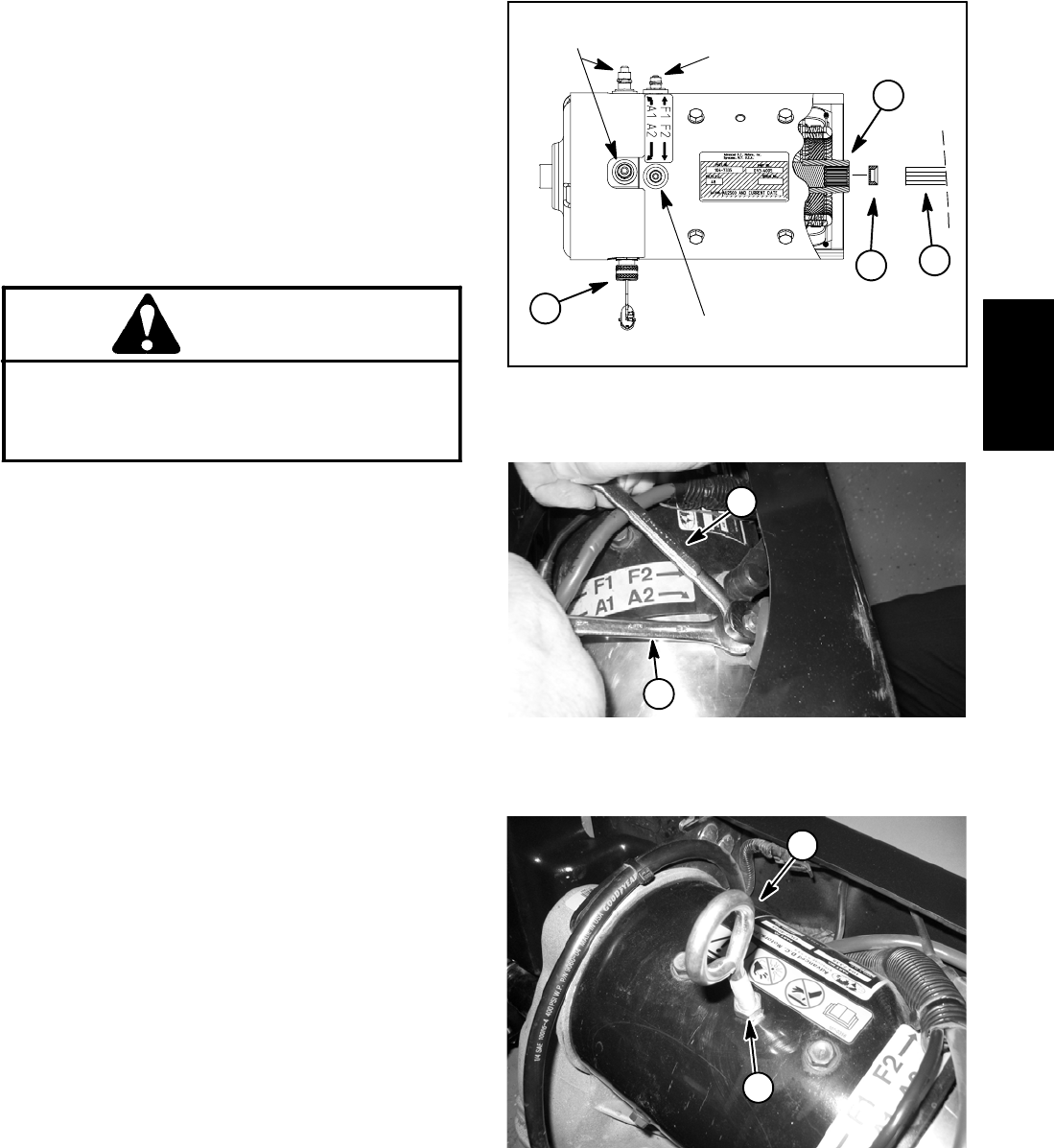
4. Disconnect wires from traction motor (Fig. 51):
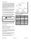
A. While retaining lower nut, remove upper nut and
wire connector from motor terminals A1, A2, F1 and
F2.
B. Unplug motor temperature sensor from vehicle
wire harness. Note location of cable tie that secures
temperature sensor wires to vehicle.
C. Position disconnected wires away from motor.
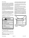
5. Remove plastic plug from rear frame to allowaccess
to socket head screw that retains fan to traction motor.
Remove screw and washer and then remove fan from
motor.
CAUTION
To prevent motor damage and personal injury,
make sure that traction motor is well supported
as itis removed. Motor weighsapproximately 62
pounds (28.1 kg).
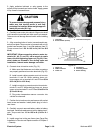
6. Support traction motor to prevent it from falling. Two
suggestions for traction motor support are as follows:
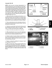
IMPORTANT: Damage to traction motor field coils
will result if eyebolt is threaded into motor housing
to far.
A. Remove silverflange head screw fromtop of mo-
tor and carefully install a 3/8 -- 16 eyebolt into motor
(Fig. 53). Thread eyebolt into motor approximately
four (4) turns taking care to not bottom eyebolt into
internal field coils. Secure eyebolt with jam nut. Use
eyebolt for support and as a lifting point for motor re-
moval.
B. Use lifting strap wrapped around motor housing
for support and as a lifting point for motor removal.
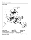
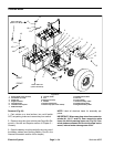
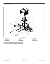
7. Remove six (6) socket head screws (item 1) and flat
washers (item 2) that secure motor to transaxle.
8. Slide motor away from transaxleto disengage motor
shaft from transaxle input shaft. Carefully lift motor from
vehicle. Take care to not damage thermal switch while
motor is removed.
9. Locate and retrieve rubber damper from motor shaft
internal spline.
10.If needed, remove two (2) roll pins from motor shaft.
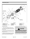
Installation (Fig. 50)
1. If removed, install two (2) roll pins into motor shaft.
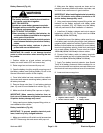
2. Make sure that rubber damper is installed into the
motor shaft internal spline with the damper flat side to-
ward the motor (Fig. 51).
1. Thermal switch
2. Motor shaft spline
3. Rubber damper
4. Transaxle input shaft
Figure 51
55 to 60 in--lb
(6.2 to 6.8 N--m)
85 to 90 in--lb
(9.6 to 10.2 N--m)
55 to 60 in--lb
(6.2 to 6.8 N--m)
1
2
3
4
1. Loosening/tightening wrench (upper nut)
2. Retaining wrench (lower nut)
Figure 52
1
2
1. Eyebolt 2. Jam nut
Figure 53
1
2
Electrical
System